
My knowledge of electronics is very basic/limited to say the least, so bear with me.....!
I'm looking to use some USB powerbanks to power some small battery operated devices. The devices are little PIR activated MP3 players so they play a message/tune when someone walks past. The in-built batteries are AAA and just won't last long enough and because there are several devices, I want a convenient recharge solution too. Where they are going, there is no mains to power them from. They do have a micro USB port though and will run happily from that without the internal batteries - hence the idea to use a USB powerbank.
The devices have an extremely low current draw when in standby (less than 1mA claimed), so needless to say, the power bank decides to switch itself off after around 35 seconds of the last PIR activation. I've found pulse circuits on the net that sit between battery and device that keep a power bank active for these sorts of low current applications and I accept that using these will mean the tiny LEDs on the power bank will stay on and contribute to the drain a little - but I still want to reduce the current consumption to an absolute minimum AND make the circuit adjustable to suit different powerbanks.
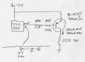
So, I'm looking to use a CMOS 555 timer (TLC555) and have pots on the timing side that give me a range of say 3-30 seconds between pulses, and a pulse of say 200mS-1 second. I'm OK with this bit - but the timing seems to dictate a PNP transistor to switch the load so the transistor is off when pin 3 is high.
My question is around the dummy load. 200mA seems to be a reasonable worst case figure for keeping power banks up, but the power bank I'm currently using seems to stay active with the device operating (around 60mA). So I want to be able to limit the current into the load resistor too - so my thinking was to just add a pot to the base so the transistor can be set to partly turn on, through to fully on - giving me a range of say 50-200mA. Any thoughts on whether this is best approach and if so, what pot value?
Thanks!
I'm looking to use some USB powerbanks to power some small battery operated devices. The devices are little PIR activated MP3 players so they play a message/tune when someone walks past. The in-built batteries are AAA and just won't last long enough and because there are several devices, I want a convenient recharge solution too. Where they are going, there is no mains to power them from. They do have a micro USB port though and will run happily from that without the internal batteries - hence the idea to use a USB powerbank.
The devices have an extremely low current draw when in standby (less than 1mA claimed), so needless to say, the power bank decides to switch itself off after around 35 seconds of the last PIR activation. I've found pulse circuits on the net that sit between battery and device that keep a power bank active for these sorts of low current applications and I accept that using these will mean the tiny LEDs on the power bank will stay on and contribute to the drain a little - but I still want to reduce the current consumption to an absolute minimum AND make the circuit adjustable to suit different powerbanks.
So, I'm looking to use a CMOS 555 timer (TLC555) and have pots on the timing side that give me a range of say 3-30 seconds between pulses, and a pulse of say 200mS-1 second. I'm OK with this bit - but the timing seems to dictate a PNP transistor to switch the load so the transistor is off when pin 3 is high.
My question is around the dummy load. 200mA seems to be a reasonable worst case figure for keeping power banks up, but the power bank I'm currently using seems to stay active with the device operating (around 60mA). So I want to be able to limit the current into the load resistor too - so my thinking was to just add a pot to the base so the transistor can be set to partly turn on, through to fully on - giving me a range of say 50-200mA. Any thoughts on whether this is best approach and if so, what pot value?
Thanks!
Attachments
-
 240.9 KB Views: 17
Last edited:


