TL072 Op amp Buffer Issues

Thread Starter

ldkimball

Joined Sep 15, 2024
4
Hi all,

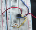
I'm using a simple voltage divider/ op amp buffer circuit to make a 2.5V reference voltage for the rest of my circuit. The VCC+ is connected to +12V and the VCC- is connected to -6V. The voltage divider by itself outputs a voltage of 2.503V but when it's connected to the buffer, the output gives something closer to 2.67V. When I connect the non inverting input to ground instead of 2.5V, it gives around 170mV. When I connect it to 5V it gives 5.17V. So it seems to be tacking on an extra 170 ish mV seemingly from out of nowhere. I've read through the data sheet several times and I'm confident I'm working well within the recommended operating conditions of the op amp. I really don't understand what I'm doing wrong here. It goes without saying that I'm an electronics beginner. I appreciate any and all help!
 

Attachments

Thread Starter

ldkimball

Joined Sep 15, 2024
4
Apologies for the messy wiring. I had a larger circuit connected and I decided to take it out to simplify things. Bottom voltage regulator is the 7905 and top one is the 7906. Black box on the top left is the DC to DC converter.


A picture of your breadboard shows us little.
Post a schematic of what you have.
 

Attachments

Thread Starter

ldkimball

Joined Sep 15, 2024
4
The missing schematic, details about the voltage reference?

View attachment 331698

Hey thanks for drawing that up! Maybe I'm reading it wrong but the first op amp doesn't lead into the second op amp and I'm only concerned with the op amp that has the 2.5V input. I was on a call when the messages came through so I didn't get a chance to draw it. I can't make a -12V rail with the supplies I have but the input offset for +12/-6 is 170mV and for +5/-6 it's the same. I'm super new to electronics so sorry if I'm misunderstanding some of the terminology.
 

sparky 1

Joined Nov 3, 2018
1,218
The first op amp has 2.5V output. It might be possible that the op amp is bad, however to know that first check supply.
Since there is no problem in the simulation. Next is examining the full schematic for an error.
In the full schematic, the power supply, the regulators, the capacitors, voltage divider the other things before the regulators need checking.
 

Ian0

Joined Aug 7, 2020
13,131
What make of TL072 are you using. They are meant to be unity-gain-stable, but the SGS-Thomson ones weren't quite as stable as perhaps they should be. Can you see any high frequency oscillation on the output?
 

MisterBill2

Joined Jan 23, 2018
27,508
On a prototype board like we see in the pictures it is entirely possible to have connections that are not perfect and thus create a bit of a voltage drop. In addition, there is the effect of "input offset voltage", which is often ignored because in many cases it does not matter. IT IS PROBABLY NOT 0.000 VOLTS, but probably within the range shown on the detailed data sheet. So there are some of the invisible things that may be causing the departure from the perfect circuit values.
Also, your supplies might not be exactly 12.000 volts and -6.000 volts. That happens quite a bit.
 

dl324

Joined Mar 30, 2015
18,326
when it's connected to the buffer, the output gives something closer to 2.67V.
  1. What is this mysterious "buffer" component?
  2. Is the opamp known to be good?
  3. Are the power supply voltages stable?
  4. Do you have decoupling on the opamp?
Didn't try tracing the second picture because the wiring is so messy and the components on the second board aren't labeled.

Why did you use two boards? The half board would have been sufficient.

Also, unless you're twisting the leads on the TO-220 devices, you're abusing the contacts in your board.

This is a discrete MOSFET voltage regulator I designed:
discreteMosfetRegulatorFinalAsBuilt.jpg
 
Top