TL071CP MAX Output Current

Thread Starter

SamR

Joined Mar 19, 2019
5,491
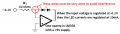
That is what I would expect, but I'm being told here that the input current equals the load current Irregardless of the feedback resistor value. Which I don't understand exactly how that happens?
1639778368690.png
There is no real output here. The R(sub)L load is being virtually grounded at the summing point and the +input current equals the -output current. On LTS, I am using the "standard op amp" model #1 and the only way the currents are mirrored is when the load (output) resistor is the same value as the input resistor. Thus, my confusion here!
 

AlbertHall

Joined Jun 4, 2014
12,625
the input current equals the load current Irregardless of the feedback resistor value. Which I don't understand exactly how that happens?
The opamp will keep the two input pins at the same voltage, in this case 0V. The input voltage will drive a current through Ri and as the opamp input current is esentially zero, that current must flow through Rf (it has nowhere else to go). The feedback resistance value will change the output voltage but not the current through Rf.
 

Thread Starter

SamR

Joined Mar 19, 2019
5,491
Aha, then the summing point becomes zero by the op amp output matching/balancing the feeback loop to counter the input. It's starting to gel a bit, thanks again Albert.
@Audioguru again The feedback resistor in this case IS the load. They are the one and same resistor.
 

Audioguru again

Joined Oct 21, 2019
6,826
The load for an opamp connects to the output and to ground. The feedback resistor does not connect to ground, instead it connects to the extremely sensitive inverting input of the opamp that will pickup a lot of interference in its connecting wire from the air.
 

AlbertHall

Joined Jun 4, 2014
12,625
Suppose that in the feedback resistor position there is only the LED of an optocoupler. Now the input is a linear resistor and the LED current is an accurate reflection of the current in that resistance. Now the LED current is linearly related to the input voltage.
 

Delta Prime

Joined Nov 15, 2019
1,311
Hello there Sr. :)up amps were pain in my behind for the longest time and reading this post I believe I'm still confused o_OBeing bombarded different examples or another way of looking at the same thing seem to help me. But I'm walking on eggshells here respectfully. If if you have already seen this I apologize but I must say it did help me along with all of my other friends trying to get me to understand it.
In physics we call it equilibrium.
https://www.allaboutcircuits.com/textbook/semiconductors/chpt-8/negative-feedback/
 

Thread Starter

SamR

Joined Mar 19, 2019
5,491
LEDs did come to mind as being something that needed constant, limited, and stable current. I think I'll throw those into my breadboarding experiment. I would like to see if or how it can, if possible, handle more than a single LED. Not sure if there is enough voltage overhead for the multiple voltage drops without going over the current limits. Optocoupler or optoisolater didn't come to mind but yes. Hopefully I can get it breadboarded before the weekend is over.
 

Thread Starter

SamR

Joined Mar 19, 2019
5,491
I started doing the math for my experiment and right off the bat found out that this little chip can't handle much power. Only ~35mW @25°C. So with a max V=15V and max I=25mA that's 375mW so something has to give. So @ Vin=7 and Rin=2k to give me -3.5mA across the load and 24.5mW. Not a whole lot to play with here. Certainly not enough for an LED... Well then let me put it all together and see...
IMG_0870[1].JPG
Ok, not what I expected. Something is not correct here. Wiring doublechecked and correct. Voltmeter on pin 6, current meter from the output of 12k resistor on pin 6 to pin 2. 2k resistor from PSU to pin 2, pin 3 grounded. +15V on pin 7 and -15V on pin 4. OK enuff for tonite...
 

Audioguru again

Joined Oct 21, 2019
6,826
Suppose that in the feedback resistor position there is only the LED of an optocoupler. Now the input is a linear resistor and the LED current is an accurate reflection of the current in that resistance. Now the LED current is linearly related to the input voltage.
I do not know why a feedback resistor is a load but here are two LEDs as the load and the opamp amplifies the input voltage enough to drive them:
 

Attachments

Audioguru again

Joined Oct 21, 2019
6,826
I started doing the math for my experiment and right off the bat found out that this little chip can't handle much power.
With a plus and minus 15V supply and its minimum load of 2k ohms, when the output voltage and the voltage across the load is 7.5V then the current in the load is 7.5V/2k= 3.75mA and its heating is 7.5V x 3.75mA= 28mW and the heating in the opamp is the the same 28mW plus 35mW of idle power= 63mW.

The power in an IC is the amount of heating it produces. Its maximum allowed internal temperature is 150 degrees C and if your ambient is 30 degrees C then the maximum heating it is allowed is 120 degrees C.
The DIP package junction to ambient rating is 85 degrees C per Watt so its max allowed power is 1.3W.
Then the above example of 63mW heats the internal chip (63/1000 x 85= 5.4 degrees C above the ambient temperature which is fine.

Your current measurements do mot match the calculations because:
1) A breadboard causes poor connections.
2) A current meter has a resistance that increases the the actual resistance that reduces the current.
It is much better to measure the voltage across the resistor then calculate its current.
 

Thread Starter

SamR

Joined Mar 19, 2019
5,491
I plan on redoing without the ammeter and simply measure the voltage drop to calculate by. I did have some qualms over using an ammeter due to the low value and was unsure as to how much it might skew the results but with them in question it is only prudent to use a better method.
 

Thread Starter

SamR

Joined Mar 19, 2019
5,491
OK, I see what is happening here. The Vo is hitting ~-12.5V and too close to the negative rail since I have it set for ±15V. Everything within that span is on spec. I also replaced R(sub)L with a decade box and kept the Vin @ 5V and everything was spot on until Vo went below ~-12.5V and too close to the rail. Lowering the Vin would help that. I am somewhat puzzled that the output voltage goes down to over -18V with a -15V rail. What I see with the fixed Vin output is typical in that as the voltage exceeds the supply current starts dropping to provide the excess overage. Thanks for the input guys!
IMG_0871[1].JPG
 

Audioguru again

Joined Oct 21, 2019
6,826
You are probably measuring the voltage across the feedback resistor and not the opamp output voltage to ground. Then when the opamp output goes as low as it can to -12.5V the input resistor has extra positive voltage across it and adds to the voltage across feedback resistor.
Again, the feedback resistor is not a load.
 
Top