Setting up the TL071CP op amp as a current output and trying to find the max output current. Found the max supply so I assume that would also be the max out?
Somewhat confused as to the Vo=0 also.
So, should I design for 1 to 2mA? Say ~1.5mA.
Thanks Albert and when I saw the short circuit current the lightbulb lit up reminding me that it has continuous short circuit protection so I can push it to max without it going up in smoke. Thanks again!
I see now why I didn't find it on the TI PDF. It is under 6.17 Electrical Characteristics: TL07xH (continued) but not under the listing for the TL071C for some reason? Yes, there are always "reasonable" limits. Didn't think of the Watts even though I know to do that for XSTRs. Thanks for the reminder!
It is an opamp, not a power amp. For most of its specs its minimum load is 2k ohms then if your supply is plus and minus 15V, its peak output current with a 10V peak output voltage is 10V/2k= 5mA.
If you have a plus and minus 15V supply, a 2k load and an output voltage at plus or minus 7.5V then its output current is 7.5V/2k= 3.75mA and its output transistor heats with 7.5V x 3.75mA= 28mW plus its small idle heating.
Sure you can smoke it if it has a low load resistance, a high output current and a high voltage across its output transistor (especially when the load is a short circuit).
Your inverting amplifier has no load (it is not a constant current source circuit) so you are measuring the current in its feedback resistor. If the feedback resistance is low then all of its output current will be in it, instead of in the load.
Your inverting amplifier has no load (it is not a constant current source circuit) so you are measuring the current in its feedback resistor. If the feedback resistance is low then all of its output current will be in it, instead of in the load.
I am working through the TI Op Amp Handbook and notice the resistor is marked R(sub)L, load resistor. The resistor in this example is the load as well as the feedback. No idea of how this may actually be used even though they gave some examples that I am not familiar with. Simply an exercise of the presented theory. Not finding the max output current the PDF section for the TL071C (it was in the section for the TL071H so I hope it carries over to the C) I did not have a clue as to what the max output current might be for this Op Amp experiment to design for. And yes, anything can be smoked if overstressed. Which I am trying to avoid! Also note the I have moved on from the "Antique" 741 to a more modern design.
Most opamps including the TL071C are designed to work with a load resistance as low as 2k ohms. A few opamps can drive a minimum of 600 ohms. 10V/2k ohms= 5mA, 10V/600 ohms= 16.7mA.
I have never seen an opamp output that has a shorted load that might draw 26mA.
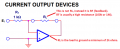
In this particular case they are. I see you found Figure 19. Inverting Amplifier as a Linear Current Output Device. Except there are a couple of notes on yours. With the summing point being the virtual ground, it is both the load and feedback resistor in this case. So, with the I(sub)L being the load current which would depend on the design or the resistive load and the necessary current across it, it then requires me to provide an input voltage across the input resistor to match the required load current. The input voltage must fall within the input voltage parameters of the Op Amp specs. But, according to the notes on your diagram, the load resistance should be a minimum of 2kΩ. Am I correct so far? Then I could select a midrange input voltage and size the input resistor to generate the matching load current or slightly more to give some overhead?
Looking at graph 6.52 adjusting temperature to 27C which corresponds to 1.3 mA can be a starting point.
select a system example at section 9.4 also keep in mind graph 9.5 VIN < 10.5V for the example applications setting gain.
Then when you turn it up watch the temperature. ( Are you exceeding the rated the MAX 2.5 mA) or do you look at graph 6.52 at 100 degrees C 1.1mA
It might be 10 mA who knows on the output but ONLY you can say what your maximum will be. When you shoot your thermometer on it you may need to glue heat sink. So the exact characteristic on the graphs may be close to an example but test and adjust the graph for your application then the math
and the graphs all work perfectly. The math may give it professional touch when your tolerances are in spec then more circuitry will also be in spec.
A maximum is how hot you want to run it within specs ? It might be a personal preference for your end goal. So we build the examples, run the tests
using what we have, sometimes we need to change out parts then we have a reliable graph without any guessing our final board usually is better. https://www.ti.com/lit/ds/symlink/tl071.pdf
YOU do not match the output current of an inverting opamp to the input current, instead the opamp does the matching automatically because the open loop gain is so high that negative feedback causes the inverting input voltage to be a "virtual ground" which has almost the same fixed voltage (0V ground in your circuit) as the non-inverting input.
An example is a 10k input resistor with +100mVDC feeding it. With a 1Meg feedback resistor the voltage gain is 1M/10k= 100 times producing an output of -10V if the power supply allows it.
Then the input current is 100mV/10k= 10uA and the output current is 10V/1Meg=10uA which is the same current as the input current. You can have an external load that is almost as low as 2K ohms and this load or no load has no affect on the output voltage.
Opamps are not supposed to have a high output current and high heating which is why they do not have a metal fin to attach a heatsink like power amps have.
Actually it is a balancing act. Mirroring the input to the output (within the limits of the op amp). The inputs equal the outputs in this case. There is no amplification. Which has me scratching my head a bit and asking why I even use an op amp?
It is a voltage amplifier and a current amplifier. My example amplifies the voltage 100 times and if the load is 2k ohms then the 10uA input creates an output current of 10V/2k= 5mA which is a current gain of 500 times.
In this instance (post #1), it is a modified voltage follower with a load in the feedback loop to give constant current. So there is no amplification. Just illustrating a modification of the voltage follower. Unless I've missed something? Hopefully I can find time today to breadboard it. Built and played with it a bit in LTS.
In this instance (post #1), it is a modified voltage follower with a load in the feedback loop to give constant current. So there is no amplification. Just illustrating a modification of the voltage follower. Unless I've missed something? Hopefully I can find time today to breadboard it. Built and played with it a bit in LTS.
Post #1 does not have a voltage follower and does not produce constant current. Instead it is a simple inverting amplifier. The ratio of the resistors determines its gain or loss.
The current in the input resistor produces exactly the same current in the feedback resistor. Then the opamp is not needed, just use the input resistor connected to ground and its current depends on its value and the input voltage, the same things happen in the opamp circuit.
Yes, that is the conclusion that I came to and scratched my head a bit about it. They mention two examples of usage " can serve as a linear meter amplifier or deflection coil driver". Just woke up and not completely coherent as yet, yes, it IS an inverted amp (not voltage follower my bad) example. So the idea here is the induced current is the feed, Irregardless of the load, is the current across the load?
Depending on the resistance ratio of the input resistor and feedback resistor, the output voltage from the inverting opamp is amplified, the same or attenuated. The current is determined with Ohm's Law.
 Facebook
 Google
 GitHub
 Linkedin


")