TL062CN Op-amp first issue

Thread Starter

maver144

Joined Jul 12, 2020
11
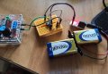
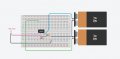
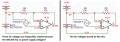
Hello, I just started my journey with op-amps. I'd like to use it to amplify XR2206 based generator. I'm trying to set it up as non-inverting amplifier. I connected it as follows.

Screenshot_11.jpg
Gain should be around ~6, and my generator outputs signal with amplitute 1-2 V adjustable. However, probing between OUT and battery mass I don't see any signal. I would be glad for any clues.
 

Papabravo

Joined Feb 24, 2006
21,225
The input to an opamp is very high impedance. That means that little to no current will flow into the input. A current source will not appreciably affect the voltage on Pin 3. Use a voltage source. The opamp will look at the voltage difference between the two inputs and adjust the output to drive the voltage on pin 2 to the same level as on pin 3.
 

Zeeus

Joined Apr 17, 2019
616
Try connecting a resistor from pin 3 to ground

There's little error in schematic tho but not wiring

Measure the voltages at pin 4 and pin 8

Also at pin 3 and 2 and 1
DC voltages
 
Last edited:

Papabravo

Joined Feb 24, 2006
21,225
As far as I'm concerned, it is voltage source.
The opamp and the simulator might not care what you think. Labeling a voltage source "I1" is more than a bit unusual. It strongly suggests that it is a current source. They are most definitely not the same thing.
 

Thread Starter

maver144

Joined Jul 12, 2020
11
I added this reference resistor, none improvement tho.

pin 8 -> 9.3 V
pin 4 -> -9.3 V
pin 1 -> 0.39 V
pin 2 -> 0.08 V
pin 3 -> 1.13 V

Here are the voltage levels. Not supposed to be like that. I should mention, its brand new part.
 

Alec_t

Joined Sep 17, 2013
14,313
On the breadboard sketch (24) there is no component connected to pin 2. I can't make out what goes where in the photo (25).
If pins 4 and 8 are shorted internally, as your voltage readings suggest, the IC is toast and the batteries soon will be.
 
Last edited:

Zeeus

Joined Apr 17, 2019
616
oh wait.. 47k?

In image it looks like 4.7k

The resistor values are correct sir?

Anyways, shouldn't be a problem

Measure your input signal again, change the op amp

You are surely making a mistake somewhere
 
Last edited:

Audioguru again

Joined Oct 21, 2019
6,691
Why does the opamp have a dual polarity supply and the XR2206 has no power supply?
If they both use a single positive supply and the opamp +input is biased at half the supply voltage and has its input capacitively coupled to the XR2206 output then it will work fine.

I see these voltages on the circuit when the opamp has a dual polarity supply:
 

Attachments

Thread Starter

maver144

Joined Jul 12, 2020
11
Why does the opamp have a dual polarity supply and the XR2206 has no power supply?
If they both use a single positive supply and the opamp +input is biased at half the supply voltage and has its input capacitively coupled to the XR2206 output then it will work fine.

I see these voltages on the circuit when the opamp has a dual polarity supply:
I'm using a module based on XR2206 cheap, its supplied with an external source. I just didn't have a clue how to present it on schematics. It has signal and ground pin, I put sine signal at (+) input and module ground to batteries supply ground.
 

Attachments

Audioguru again

Joined Oct 21, 2019
6,691
I show the opamp with the same DC voltage on both inputs. Then the output voltage will be +6.44VDC and the waveform will have its top clipping if the input signal is increased.
 
Top