Time delay relay issues

Thread Starter

Naznooz

Joined Feb 6, 2025
7
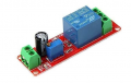
Hi all, recently I purchased a set of 5pcs 12V 1-10 seconds time delay relay. I am having the same problem with all 5 units, when I connect the 12VDC to the input, the replay couples and does not disconnect; I tried turning the timer in both directions to add or decrease the time but nothinb happens. Any help in finding out if I am doing anything wrong or what needs to be done to remedy this?!
 

Tonyr1084

Joined Sep 24, 2015
9,744
Welcome to AAC.

Provide a link to what you bought so we can have a look.

Also, a picture of how you have them hooked up would be helpful. A schematic if you have one.
 

Externet

Joined Nov 29, 2005
2,627
Yes, we need to know that relay type.

Always disliked the lack of terminology with delay relays. Specially when no data sheets/instructions attached.
When power is applied; does it take time to change state ?
Or, when power is applied, acts and takes time to release ?
Or, is it the type that cycles from one state to the other after a set time ?
Or, cycles from the other state to the initial state after a set time ?

With timers and trigger pins, with no action at power-up;
the output goes high and returns to 'low' after a time ?
or, goes 'high' after a time ?
or, goes 'low' after a time,
or, the trigger has to stay present for a given time to act,
or, obeys instantly to the trigger and starts counting the time with no action until then times-out ?,
or, the trigger does nothing if in one state but does in the other...
or, with action at power up ?

Is there a key/terminology/lettersoup to select/order what action is wanted from the device ? :rolleyes:
 

sghioto

Joined Dec 31, 2017
8,634
Hi all, recently I purchased a set of 5pcs 12V 1-10 seconds time delay relay.
Theses Modules are probably what the TS bought from Amazon or maybe AliExpress.
You connect 12 volt power and the relay activates for a duration set by the pot.
Not much else to say about it, either they work or not. Might check the solder connections on the pot and others.
1738869836858.png
 

Thread Starter

Naznooz

Joined Feb 6, 2025
7
Theses Modules are probably what the TS bought from Amazon or maybe AliExpress.
You connect 12 volt power and the relay activates for a duration set by the pot.
Not much else to say about it, either they work or not. Might check the solder connections on the pot and others.
View attachment 342070
Thank you Sghioto, yes, this is exactly what I got from Aliexpress, a set of 5. As you mentioned it either works or not but all 5 are bad! May be there is something that I am doing wrong. Once I connect to 12VDC the relay closes immediately and stays closed until I shut it off. Tried keeping it for 60 seconds nothing happens, it stays engaged. Any idea what could be wrong. As it mentions the adjustable resistor should either increase or decrease the time, yet nothing happens. All 5 do the same thing.
 

Thread Starter

Naznooz

Joined Feb 6, 2025
7
Welcome to AAC.

Provide a link to what you bought so we can have a look.

Also, a picture of how you have them hooked up would be helpful. A schematic if you have one.
Here is an image of what I bought, got it from Sghioto who posted the image in this thread. It says that it is a simple connection to 12VDC yet once powered the relay engages and stays so until I shut power off. All 5 did the same. Any possible trouble shooting? Thanks
1738885156665.png
 

Thread Starter

Naznooz

Joined Feb 6, 2025
7
When 12 volts is applied do the LEDs light up?
My first suspicion would be the timing pot.
Check solder the connections on pot.
Hello Sghioto, Yes the LEDs light up immediately and the relay engages. By the timing pot you mean the adjustable resistor (potentiometer), no? Is it possible to check the contacts on the potentiometer or even change it to a different type with similar value?
 

sghioto

Joined Dec 31, 2017
8,634
Hello Sghioto, Yes the LEDs light up immediately and the relay engages. By the timing pot you mean the adjustable resistor (potentiometer), no? Is it possible to check the contacts on the potentiometer or even change it to a different type with similar value?
Yes the adjustable resistor.
Could remove it and replace with a resistor if the delay time can be constant.
 

Tonyr1084

Joined Sep 24, 2015
9,744
Wondering if these are factory rejects and have been wholesaled for the purpose of someone wanting to disassemble and use the parts for another project. Only, the person who bought these rejects has turned around and put them up for sale. Did you read the reviews? FIVE stars and only TWO reviews could be easily something a friend or two may have done to make the item look legitimate. I never trust products with only a few reviews. The more the reviews the more legitimate they are.
 

sagor

Joined Mar 10, 2019
1,047
I wonder if the pot is a 10 turn device. In which case, one may have to turn the head several times to get a few seconds delay.
Try turning the pot 10 times in one direction and test again. Then turn 10 times the other direction and test once more. If both LEDs come on instantly both times, then there is something defective, most likely the pot, but could be a faulty 555 timer as well.
Interesting about the picture on Amazon, 5 pictures have the head of the pot towards the Vcc connector. One picture shows the head of the pot towards the relay.
 

Tonyr1084

Joined Sep 24, 2015
9,744
I wonder if the pot is a 10 turn device.
Yeah, I had the same thought.
Try turning the pot 10 times in one direction and test again. Then turn 10 times the other direction and test once more.
Yes, you CAN turn it many many times in either direction, far beyond the 10 turns and it WILL NOT DAMAGE the pot.

It makes sense to have a 10 turn pot for such a short variable time setting. Using a 85˚ turn pot would mean a very course adjustment and achieving the difference between 2 and 3 seconds would be virtually impossible.
 

sghioto

Joined Dec 31, 2017
8,634
That would explain why it doesn't work.
Only 2 pins needed.
One to Vcc and the other to pins 2-6 on the 555. Use the middle pin of the pot and one of the other pins.
Figure will need to cut some traces and add some wiring to complete.
 
Last edited:

Tonyr1084

Joined Sep 24, 2015
9,744
I tested the pot connections using a multimeter, only the GND is connected.
The VCC does not show any connection.
{Quote modified by TonyR1084}
You're saying you get 12 volts at Node 1 but not at Node 2?
Screenshot 2025-02-08 at 9.02.38 AM.png
Set your test meter to Volts DC. Connect black lead to "Node G". Using your red lead, test the following nodes:
Measure voltage at Node 1. What did you get?
Measure voltage at Node 2. What did you get?
Measure voltage at Node 3. What did you get?
Measure voltage at Node 4. What did you get?
Measure voltage at Node 5. What did you get?
You SHOULD get 12V at all five nodes. This drawing has been slightly modified. It shows all VCC connected. They've been labeled Nodes 1 through 5. If you don't have 12V on all five nodes then the PCB is defective. Either return it for a refund OR make your own connections between the nodes. If 12V is present at Node 1 but not at Node 2 then jumper Nodes 1 & 2. All five nodes should read 12V.

It's possible you're testing 12V at what I'm calling node 1 at the connector pin it's possible the defect is right there. Determine where the voltage is going and where it is not. Let us know what you find.
 
Last edited:
Top