three antennas?

Thread Starter

mik3ca

Joined Feb 11, 2007
189
I finished my receiver last night, and the quality is fair.

I did experiment with my receiver, and noticed that when I add an antenna to my speaker connection point, the station fades out. The same applies if I add an antenna directly to +ve. The radio is connected to my computer through end-to-end speaker cable.

Other than connecting the speaker connections together with a capacitor, is there any other way I can prevent interference from happening?

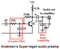
My guess is to make a PI filter, and I think I should make it pass anything between 120Hz and 20Khz.

I notice the interference the most when I move my long speaker wire around, or when my long speaker wire is in the wrong position.
 

Audioguru

Joined Dec 20, 2007
11,248
Your super-regen circuit you posted before does not have a lowpass filter. So The RF is fed to the audio amplifier.
Andersen's super-regen circuit has a lowpass filter and it has an additional filter capacitor at the output of his audio preamp he says he added "to stop instability".
Your circuit has instability.

An FM radio needs a de-emphasis lowpass filter anyway to cancel the pre-emphasis (treble boost) by all FM and TV stations. It also reduces the ultrasonic high frequency from the quenching oscillator.
I think you removed the quench oscillator from your circuit so it needs a manual sensitivity adjustment. Its sensitivity will change when the supply voltage changes.

I think your circuit also needs a ceramic high frequency supply bypass capacitor like the other circuits have because your 1000uF electrolytic capacitor is an inductor (not a capacitor) at high frequencies.
 

Attachments

Thread Starter

mik3ca

Joined Feb 11, 2007
189
that low-pass filter that you boxed was something I was thinking about adding to my circut, but the problem with those values is that according to my math, I only get 723Hz

The equation I used is:

1 / 2 * pi * R * C

so I'm wondering, why should 723Hz be the maximum frequency that can be passed through to the rest of the circuit when the maximum audio (that our ears can hear) frequency is over 15KHz?

or is my math off?

I was also thinking about that last boxed capacitor that I can tie across my speaker output. How do I calculate the lowest value that provides the least stability?

I find that if that value is too much, volume will be too low.
 

Audioguru

Joined Dec 20, 2007
11,248
Hi Mike,
You are correct. The first lowpass filter reduces frequencies above 727Hz but since it is fed from an additional resistance then its cutoff frequency is lower.
The second filter cutoff frequencies above 724Hz so both filters add and cut most high frequencies. The designer must have wooden ears.

The stereo sidebands of FM stereo extend up to 53kHz. Then the lowpass de-emphasis filter cuts the higher audio frequencies back down to normal.
FM and TV sound in North America uses 75us for its high frequency pre-emphasis and de-emphasis. Then the treble is boosted gradually above 2133Hz during transmit and is cut gradually above 2133Hz during receive. In Europe they use 50us.

You should not short-circuit the output of your amplifier with a capacitor because the output resistance of the amplifier is very low. The capacitor shorts the output at high frequencies which creates high currents. A lowpass filter is used at a point in a circuit that has a fairly high resistance like at the input of your amplifier.
 

Thread Starter

mik3ca

Joined Feb 11, 2007
189
Hi Mike,
You are correct. The first lowpass filter reduces frequencies above 727Hz but since it is fed from an additional resistance...
you mean the resistance of the material that connects the capacitor and resistor together?

The stereo sidebands of FM stereo extend up to 53kHz.
...
Is there any other frequencies of importance I need to know about?
 

Thread Starter

mik3ca

Joined Feb 11, 2007
189
The stereo sidebands of FM stereo extend up to 53kHz. Then the lowpass de-emphasis filter cuts the higher audio frequencies back down to normal.
FM and TV sound in North America uses 75us for its high frequency pre-emphasis and de-emphasis. Then the treble is boosted gradually above 2133Hz during transmit and is cut gradually above 2133Hz during receive. In Europe they use 50us.
but I still don't get why I should make a low-pass filter to 723Hz.
To me, it would make more sense to make a low-pass filter to 20Khz because then the audio frequencies can get through. Do you agree that I should change the values of the filter?
 

SgtWookie

Joined Jul 17, 2007
22,230
The low-pass filter is not a sharp cutoff; it simply attenuates the higher-frequency signals. The higher the frequency, the greater the attenuation.

Without the low-pass filter you would have very little bass, some midrange, and very loud treble, making the output sound very "tinny". The low-pass filter serves to "flatten out" these inequalities, making for a much more natural-sounding frequency response.
 

Thread Starter

mik3ca

Joined Feb 11, 2007
189
So am I being told that I can ignore 732Hz to 20Khz for the audio frequencies?

It seems abnormal to me to cut off more than 1/2 the audio frequencies.

What about the highest-pitched note?
I don't know if it can go in 732Hz.
 

SgtWookie

Joined Jul 17, 2007
22,230
Mike,

This isn't a sharp band-edge filter.

You're not throwing the remaining higher frequency audio away; you're simply re-adjusting it to the proper levels by attenuating them back to normal.

Try it without the low-pass filter, and then with the filter.
 

SgtWookie

Joined Jul 17, 2007
22,230
Have a look at the attached.
It's a single-pole Bessel 1kHz filter I threw together using TI's free Filter Pro software. I used 1kHz because the plotting function cuts off at 10kHz for low pass filters below 1kHz.

Don't let the op amp confuse you - it's wired for unity gain.

The green trace is attenuation in dB.
 

Attachments

Audioguru

Joined Dec 20, 2007
11,248
Andersen's super-regen radio is designed to pickup aircraft communications that are AM and have a flat frequency response (no pre-emphasis like FM and TV stations have) of 300Hz to 3kHz.
The two lowpass filters in his receiver severely cut high audio frequencies since 2900Hz is cut 24db which is 1/16th and 5800hz is cut 36dB which is 1/63rd.

The first lowpass filter is supposed to be designed to reduce the ultrasonic quenching oscillator which is at about 25kHz.

An FM radio in North America has de-emphasis which is -3dB at 2133hz, -6dB at 4266Hz, -12dB at 8532hz and -18dB or more at 17kHz. Then you won't hear the 19kHz stereo pilot tone. The FM transmitter has pre-emphasis which boosts the high audio frequencies oppositely.
 

Thread Starter

mik3ca

Joined Feb 11, 2007
189
Andersen's super-regen radio is designed to pickup aircraft communications that are AM and have a flat frequency response (no pre-emphasis like FM and TV stations have) of 300Hz to 3kHz.
so the carrier can be like 100+Mhz, and his detector outputs a frequency set between 300Hz and 3kHz, and this low-pass filter will then make it so that the output frequency range is between 300Hz and 732Hz?

The first lowpass filter is supposed to be designed to reduce the ultrasonic quenching oscillator which is at about 25kHz.
then I think a 25Khz filter would work better in this situation.

An FM radio in North America has de-emphasis which is -3dB at 2133hz, -6dB at 4266Hz, -12dB at 8532hz and -18dB or more at 17kHz.
so should I make my low-pass fiter at 17kHz?
 

SgtWookie

Joined Jul 17, 2007
22,230
Mike,
I don't think you're interpreting correctly what Audioguru is trying very hard to tell you.
Andersen's radio is designed to pick up AM radio communications, which have no pre-emphasis; or a flat frequency response.

On the other hand, you are attempting to pick up FM broadcast signals, which DO have pre-emphasis; in other words, a non-flat frequency response; the higher frequencies have an amplified signal.

A very slight addition/rewording of Audioguru's post may make this more clear:
For North America, an FM radio receiver has de-emphasis which is -3dB at 2133hz, -6dB at 4266Hz, -12dB at 8532hz and -18dB or more at 17kHz. There is also a 19kHz stereo pilot tone. The FM transmitter has pre-emphasis which boosts the high audio frequencies oppositely, or +3dB at 2133hz, +6dB at 4266Hz, +12dB at 8532hz and +18dB or more at 17kHz.
You see, without the low-pass filter you would be listening to a screechingly loud stereo pilot tone, extremely loud treble, very loud high-midrange, loud midrange, amplified low, midrange - and practically non-existant bass.

It would not be a pleasant listening experience.
 

Thread Starter

mik3ca

Joined Feb 11, 2007
189
I guess that means I need to make a special AGC circuit to make the higher frequencies at the same volume as the lower one. And you were right, I was a little confused with Audioguru's answer. Thanks for clearing it up.

Does anyone know of the "simplest" AGC circuit I can add to my circuit?
 

SgtWookie

Joined Jul 17, 2007
22,230
I guess that means I need to make a special AGC circuit to make the higher frequencies at the same volume as the lower one. And you were right, I was a little confused with Audioguru's answer. Thanks for clearing it up.

Does anyone know of the "simplest" AGC circuit I can add to my circuit?
I'm afraid that you are still not quite understanding it.

An AGC circuit would not discriminate between various audio frequencies; only the overall gain would be adjusted.

That is the purpose of the "low pass" filter. The very name "low pass" may be confusing you. This is not a "brick wall" response filter, where everything above the band edge is thrown away; it is a very gradual attenuation; the higher the frequency, the greater the attenuation, but over a rather broad range of audio frequencies.

Take a look at the filter response I posted earlier today. That might help you understand a bit better.
 

Thread Starter

mik3ca

Joined Feb 11, 2007
189
Ok, then I will use a low pass filter.

I can see that several combinations of R and several combinations of C (when made into a filter) can produce the cut-off frequency.

Personally, I find that a ridiculously low value for R and a higher value for C is the best, since more of the signal can pass through.

However, I don't know the absolute best values. I think that the slope that you showed me earlier can be adjusted by changing R and C, even if the cut-off frequency is not changed.

What do you think I should pick for R and C for the filter and why?
 

Audioguru

Joined Dec 20, 2007
11,248
You cannot use a low value for the series resistor and a high value for the capacitor to ground in a lowpass filter. Because it shorts to ground the output of whatever drives it.
The resistor must be at least double the output resistance of whatever drives it for a reasonably low loss, and 10 times the output resistance for low loss. The resistor also must be about 1/10th the resistance of the circuit it feeds.

Then you will have a first-order lowpass filter that reduces the level above cutoff at 6db per octave. That is the slope of a filter with only one RC.
If your radio has a 25kHz quenching oscillator to automatically adjust its RF gain to be max, then it will be reduced to a level that won't affect the audio amplifier.

Only use one RC lowpass filter. Several combinations cause the cutoff slope to be steeper and the cutoff begins at a lower frequency which are not wanted.

Attach your entire circuit for us to see the best location for a lowpass filter.
 

Thread Starter

mik3ca

Joined Feb 11, 2007
189
Look at the attachment for my circuit. The yellow section is what I recently added, and it allowed me to tune into 103.5, but not perfectly. Without the yellow section, I couldn't tune any part of it in. The section in green is my coupling. I had to add an inductor as a filter.

I know that an RC filter may be suggested, but according to audioguru, R should probably be at least 20K. 20K can suck up alot of the signal which is why I think I should make an LC filter instead of an RC filter. What do you think I should do? use RC or LC and why?

I only want to concentrate on the yellow and green sections because they are causing the most trouble.
 

Attachments

Top