three antennas?

SgtWookie

Joined Jul 17, 2007
22,230
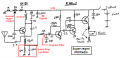
Well, in that case you'll need a series resistor of around 2.5k, an 0.53057 H inductor also in series, and a 2.5k resistor in shunt. That'll give a pretty nice attenuation from 0dB @ 0Hz, 10dB @ around 4kHz, 15dB @ 9kHz, and 20dB down by 16kHz.

You're going to have to wind your own inductor though, I'm afraid.

Get a 1/4" diameter hardwood dowel, about 26" long. Put a large cardboard disk 1" from each end. Get out your 20 gauge magnet wire supply, and wind on 20,701 turns, 750 turns per level for 27.6 levels, which will take about 5969.47 feet of wire. It'll weigh about 18 1/2 lbs when it's all wound on there.

That's for a corner frequency of 1.5kHz.

If you want your corner frequency lower, look for an old flathead Ford straight six block to use as a core.

Here's an online LC filter designer if you'd like to experiment:
http://www-users.cs.york.ac.uk/~fisher/lcfilter/

Here's an online inductor calculator program:
http://www.lalena.com/Audio/Calculator/Inductor/
 

Audioguru

Joined Dec 20, 2007
11,248
Hi Mike,
The green LC filter passes 25.3kHz and blocks all other frequencies because it is series resonant.

The yellow transistor is an emitter-follower but it is not turned on because its base has no bias current.
I fixed the yellow transistor and added a lowpass filter.

C1 and C4 are electrolytic inductors at VHF frequencies instead of capacitors.

The quenching oscillation parts have been removed from the emitter of the RF transistor. If the RF transistor oscillates, the circuit is a regen receiver instead of a super-regen receiver.

I added a 10k source resistor and 10uF coupling capacitor to your power amplifier and simulated it.
The 3.3M resistor value is too high so the operating point of the output is at 7V instead of at 4V.
The 2N2222 transistor at the output does not match the 2N2907 transistor.
Two diodes are needed in series to reduce the severe crossover distortion.

The other electrolytic capacitors have values much too high. C5 is 1000uF and is across R4 which is 2.2k ohms. Their frequency response is flat down to about 0.4Hz. If you have a very good speaker then C5 should be 100uF.
 

Attachments

Thread Starter

mik3ca

Joined Feb 11, 2007
189
I made some changes to my circuit. The updated version is below and it still doesn't work.

I have a problem adding a resistor in the signal line because doing so makes the receiver less sensitive.

In the new circuit, the floating transformer wires on the far right connect to the microphone jack on my computer.

The inductor L1 (in parallel with the tuning capacitor) was meant to be 1uH, not 0.1uH. Now that I think about it, I think L1 should be as small as possible.

Is there a way I can make the filter Audioguru suggested using an inductor instead of a resistor without negatively affecting the rest of the circuit?

also, that common-collector stage did not really make a difference in my circuit, so I took it out.

I forgot to ask a question.

Why is it that as soon as I include the transformer on the right, the station comes in more clear, and oscillates at about 3 times per second?
 

Attachments

Audioguru

Joined Dec 20, 2007
11,248
Hi Mike,
I don't know what your circiut is.
It is not a super-regen because you removed the quenching oscillator parts from the RF transistor's emitter. The "super" is the quenching oscillator that keeps the RF gain very high automatically until it is overloaded.
It might be a regen radio that oscillates but it doesn't have a manual sensitivity adjustment to control positive feedback.

The extremely high value electrolytic capacitors are not capacitors but are actually inductors at VHF frequencies.

It might be a crystal radio.

L3 and C3 are not a lowpass filter.
The value of L3 is much too low to affect audio frequencies and the value of C3 is much too high. They are series resonant which blocks most frequencies and passes one (25kHz). A lowpass filter passes low frequencies and blocks high frequencies.

Did you make one of the super-regen radios that you posted? Did it work?
 

SgtWookie

Joined Jul 17, 2007
22,230
While the center frequency of the L3 and C3 series network is vaguely around 25kHz, the values selected for L and C are such that SOME attenuation is only realized below 100Hz and approaching the GHz range. However, C3 is of such a large value that its' inductance is likely much larger than that of L3, so it's rather difficult to determine what the actual upper corner frequency is.

You might think I was just joking around with the inductor specifications I posted before; I wasn't - except for the part about using a block from a flathead Ford straight 6as a core. Inductors for audio frequency filters are MASSIVE and expensive, which is why resistors are preferred.

D2 is still missing.

Your antenna length of 27" is for the AM aviation frequencies; it is too short for the commercial FM broadcast band. It should be 34" for optimal coverage throughout the range.

If TR2 is actually a center-tapped audio impedance matching transformer, you are squandering the opportunity to build a class A output amplifier.

Rather than continuing in this project for the moment, why don't you build the radio that Audioguru was so kind to provide the schematics and even photos of the finished project; something that is known to work, and work well?

Mike, it's obvious that you like to tinker with things. So do the rest of us on here. That's good.

However, you seem to still be disregarding good advice that has been given (ie: D2 still missing) and repeated suggestions to build a tested design, a functional radio with good, solid, well-thought-out design aspects like Audioguru has so kindly provided, instead of attempting modifications that "seem like a good idea" to you?

Now something from my early electronic experiments that directly relates to what you're doing:
In the late 1960's, I saw an article in a now-defunct magazine called "Popular Electronics" about building an electronic mosquito repeller, using a 9v battery, a couple of transistors, a few resistors, a potentiometer w/switch and a piezo earphone for both the resonator and the "speaker". I thought this would be the greatest thing since 5-cent ice cream cones, and set about obtaining all the parts to build it, but I was going to make it even LOUDER, and drive the mosquitoes away from the entire neighborhood. So, I added an amplifier stage to it.

I spent hours designing the circuit board by hand, using resist pens on the copper plating, drilling the holes and soldering in the components, designing the enclosure, fabricating a clip from aluminum stock so I could hang it on my belt, and I must say that I did a nice job with what was available in those days.

However, the amplifier stage isolated the piezo element from the oscillator stage, and it didn't work. It was a failed "redesign". That was a painful lesson, but I learned from it.

What concerns me is that you don't seem to be learning, as you are not only continuing the same mistakes, but are compounding them by additionally making seemingly random changes.

Mike, you really have to stop doing that.

Please do yourself and those trying to help you a huge favor by building Audioguru's radio PRECISELY according to his schematics/assembly photos/materials list. If you feel you have to change ANYTHING due to lack of availability (like you can't get the exact transistors specified or similar) then ASK. Everything is in there, in it's place for a reason. There isn't anything "extra" that can be cut out without a performance penalty. Nothing needs to be added for "more performance".

Just build it.
 

Thread Starter

mik3ca

Joined Feb 11, 2007
189
D2 is still missing.
Sorry, I was rushing at the time I made the post. I did actually try it with two diodes in series, and it did not make a difference.

Your antenna length of 27" is for the AM aviation frequencies; it is too short for the commercial FM broadcast band. It should be 34" for optimal coverage throughout the range.
I'll have to try this.

Rather than continuing in this project for the moment, why don't you build the radio that Audioguru was so kind to provide the schematics and even photos of the finished project; something that is known to work, and work well?
I only have a limited set of parts, and as you have seen in my last schematic, I was using some of his ideas (like making the resistors that form part of the bootstrap network equal)

I have attempted all of the circuits I have posted. The reception is OK, but the sound quality is something that needs to be worked on. So far, I am able to pick up treble sounds ok, but as soon as the base comes in, I get distortion.

What concerns me is that you don't seem to be learning, as you are not only continuing the same mistakes, but are compounding them by additionally making seemingly random changes.
Not quite random.

I'll explain why i did everything I did:

I used the inductor instead of the series resistor because more of the signal can pass through to the next stage. The 22K resistor takes alot of the signal away. I want to minimize sensitivity loss.

I attempted to connect a 3nF capacitor from ground to the end of the resistor like Audioguru said, but I was unable to pick up any distant stations.

I used high value capacitors across the power supply to keep stability.

and I used a high value coupling capacitor so that more of the signal can pass through.

I used a high capacitor from base to ground (of the first RF NPN) to collect the signal from the antenna and store it longer. It seems that a certain value is most correct. A value too low causes a remote station to mix with more whitenoise, a value too high causes a remote station to come in, but may mix with a local station next to it.

I don't have a 2N3906 transistor.

I am afraid to use the 2N3904 and 2N3906 for the push-pull amplifier stage, because the signal from the previous stage would get injected into it, and I wanted to make sure they won't blow up. A 2N3904 cannot handle as much current as a 2N2222.

The reason why I may show denial to some of your ideas is because I only have a limited supply of parts, and I don't want to knowingly blow anything up. For the inductors, I only have 50uH, 0.18uH and 0.1uH.

I was wondering, why is a low-pass filter better than a band-pass filter here?
I find a band-pass filter better since it can (at least try to) attenuate 60Hz and several Mhz.
after all, 60Hz is the powerline frequency.
 

Audioguru

Joined Dec 20, 2007
11,248
I did actually try it with two diodes in series, and it did not make a difference.
I showed simulations with severe crossover distortion with one diode and low or no crossover distortion with two diodes. ALL audio amplifiers like that one have two diodes.

So far, I am able to pick up treble sounds ok, but as soon as the base comes in, I get distortion.
It is a narrowband AM radio that does not have a wideband FM detector.
No wonder loud bass sounds are distorted.

I used the inductor instead of the series resistor because more of the signal can pass through to the next stage. The 22K resistor takes alot of the signal away. I want to minimize sensitivity loss.
I showed a lowpass RC filter feeding the very high input resistance of an emitter-follower for virtually no signal loss. Then the output of the emitter-follower feeds the fairly low input resistance of the power amplifier.

You did have an emitter-follower but it was not biased correctly.

I used high value capacitors across the power supply to keep stability.
A high value electrolytic capacitor smooths the supply voltage at audio frequencies. Low value (0.001uF to 0.01uF) ceramic disc capacitors with very short leads are a good VHF supply bypass that is needed in addition to the electrolytic bypass capacitor.

I used a high value coupling capacitor so that more of the signal can pass through.
Most of your coupling capacitors were not calculated properly so their values are far too high. When the capacitive reactance of a coupling capacitor is equal to its load resistance then the signal level is reduced a little (-3dB).

I used a high capacitor from base to ground (of the first RF NPN) to collect the signal from the antenna and store it longer.
A capacitor stores DC, not AC. The RF signal is AC.

It seems that a certain value is most correct. A value too low causes a remote station to mix with more whitenoise
It is a regen circuit that oscillates and produces noise and interference. You removed the parts that make it automatically adjust its senitivity and now its sensitivity depends on the inductance of the capacitor at the antenna to ground.

a value too high causes a remote station to come in, but may mix with a local station next to it.
It has only a single tuned circuit so its selectivity is poor. Real radios have many tuned circuits for good selectivity.

I am afraid to use the 2N3904 and 2N3906 for the push-pull amplifier stage, because the signal from the previous stage would get injected into it, and I wanted to make sure they won't blow up. A 2N3904 cannot handle as much current as a 2N2222.
My last amplifier has 2N3904 and 2N3906 200mA transistors driving only 8mA into the bases of the 2N4401 and 2N4403 600mA output transistors that drive the 8 ohm speaker with a peak current of 400mA. Nothing will blow up but the little output transistors will get very hot if the output is at a continuous high level into 8 ohms.

I was wondering, why is a low-pass filter better than a band-pass filter here?
I find a band-pass filter better since it can (at least try to) attenuate 60Hz and several Mhz.
after all, 60Hz is the powerline frequency.
FM Radios do not receive 60Hz interference from power lines. AM radios might.
FM stations broadcast audio frequencies from 50Hz to 15kHz (-3db) and there is still plenty of output at 30Hz.

All FM radios have an RC 2133Hz single pole lowpass filter in North America and an RC 3200Hz lowpass filter in Europe for de-emphasis.
 

Thread Starter

mik3ca

Joined Feb 11, 2007
189
So I thought I might as well try your way just to see what happens...

the moment I changed my inductor to a low-pass filter consisting of a 27K resistor and a 1nF capacitor (using Audioguru's arrangement) was the moment I had to play with other values.

It seems that I had to make the capacitor connected to the first NPN's base 10nF and the coupling capacitor 10nF in order to pick up the station clearly. The problem now is that the volume is WAY too low. (I knew there was going to be a problem).

How do I increase the volume?
 

Audioguru

Joined Dec 20, 2007
11,248
Hi Mike,
Maybe you can increase the volume by changing your regen radio into a super-regen radio which automatically adjusts its sensitivity. Or by adding a regen control so you can adjust the amount of RF positive feedback for better sensitivity. Or by adding RF supply bypass capacitors. Or by putting the tuning tank at the collector of the RF transistor where it belongs and like all the other super-regen radios on the web.

It is an AM radio. The "A" in AM is Amplitude. The amplitude is the strength of the signal and it determines the volume. An AM radio has an "automatic-volume-control" circuit so that weak AM stations are the same volume as strong AM stations.

An FM radio has the frequency deviation determining the volume, not signal strength if the radio is any good. A weak station has the same volume as a strong station.

The input resistance of your power amplifier is about 2.2k ohms. Using a 27k series resistor in the lowpass filter reduces the level to 2.2k/27k= 8.1%. Using a 10nF coupling capacitor produces a low frequency cutoff of 548Hz so the bass frequencies are gone.
You need the lowpass filter to feed the very high input resistance of an emitter-follower transistor like I posted to avoid the loss in volume and the loss of bass frequencies.

Here is another super-regen radio circuit. It has the usual Colpitts oscillator with the tank at the collector (unlike yours) and has the usual quenching oscillator parts at the emitter (unlike yours). It also has the usual RF bypass capacitor (unlike yours).
It has a manual regen control that is used as its volume control. The author says it picks up FM stations 80km away.
The lowpass filter cuts more high frequencies than a normal FM radio to reduce interference beats of its quenching oscillator (about 25kHz) with the stereo subcarrier (around 38kHz) and SCA (around 67kHz) broadcasted.
 

Attachments

Thread Starter

mik3ca

Joined Feb 11, 2007
189
wait a sec...

Did you not tell me in an earlier post that the resistor (which is part of the low-pass filter) must be twice the load resistor?

In that last circuit, the filter resistor is 15K and the load resistor is 10K.

15K is not double 10K.

Would it be beneficial for me to reduce the 10K resistor to provide more strength?

I'm thinking there has to be a reason why 10K and 15K was chosen here instead of maybe 4K and 6K, because the way I see it, it is the 15K resistor that cuts the volume.

and one more thing. Why is it that the bias resistors (1K / 5K pot / 1K) are so low?
Mine are at 400K.
 

Audioguru

Joined Dec 20, 2007
11,248
wait a sec...

Did you not tell me in an earlier post that the resistor (which is part of the low-pass filter) must be twice the load resistor?

In that last circuit, the filter resistor is 15K and the load resistor is 10K.

15K is not double 10K.
The lowpass series resistor must be at least twice the value of whatever drives it. 10 times is preferred.You have it driven from a 10k collector resistor instead of the very low emitter resistance of a Colpitts oscillator. So it should be at least 20k. You have 27k which is fine.
My last circuit has it driven from the very low output resistance of the emitter of the RF transistor.

Its load resistance should be 10 times its value (270k ohms) but you have it driving the 2.2k input resistance of your power amplifier instead of the very high input resistance of the emitter-follower transistor that I posted. So yours is a voltage divider with a huge signal loss.
My last circuit has the 15k lowpass filter resistor driving the 15k input resistance of the transistor amplifier so the level is cut in half. It has plenty of voltage gain so the small loss doesn't matter.
Your circuit has the high gain audio transistors in the original project removed.

Would it be beneficial for me to reduce the 10K resistor to provide more strength?
I don't know why your RF transistor has a collector resistor. I don't know why your RF transistor has audio at its collector. All the other super-regen radios have the audio from the low resistance emitter.

I'm thinking there has to be a reason why 10K and 15K was chosen here instead of maybe 4K and 6K, because the way I see it, it is the 15K resistor that cuts the volume.
This audio amplifier circuit has much more input resistance and gain than your circuit.

one more thing. Why is it that the bias resistors (1K / 5K pot / 1K) are so low?
Mine are at 400K.
Because this RF transistor operates from only 3V and has enough current to work properly. Its resistors allow its current to be changed to adjust its sensitivity. Yours doesn't have enough current and it has a high value collector resistor.
 

Thread Starter

mik3ca

Joined Feb 11, 2007
189
...but you have it driving the 2.2k input resistance of your power amplifier...
How is my input resistance 2.2k?
I thought it was at 2.2M

My last circuit has the 15k lowpass filter resistor driving the 15k input resistance of the transistor amplifier...
I see the 15K resistor in the filter, but how is the transistor input resistance 15K?

...It has plenty of voltage gain...
then I think I should raise the value of a load resistor.

I don't know why your RF transistor has a collector resistor.
If I am not mistaken, in an amplifier, gain = collector resistor / emitter resistor. Since my emitter has a ridiculously small amount of resistance, (because of the tank circuit), the gain should be substantially high.

I don't know why your RF transistor has audio at its collector.
I wanted to make sure that there is a signal entering the power amplifier. If I connected it at the emitter, then I'm basically grounding the input in my circuit because the emitter is grounded through the tank.

All the other super-regen radios have the audio from the low resistance emitter.
It seems that in your last circuit, the resistance feeding the emitter is the same, but the only thing different is that a capacitor is connected across it.

I think I will adjust my capacitor connection, just to see what happens. I had it tied to the base, but now I think I should just connect it in parallel with my resistor, just to see what happens.

This audio amplifier circuit has much more input resistance and gain than your circuit.
How so?
 

Audioguru

Joined Dec 20, 2007
11,248
How is my input resistance 2.2k?
I thought it was at 2.2M
How transistors work:
The base-emitter of a transistor is a conducting low resistance diode, not a very high input resistance FET. The emitter is bypassed so it is not a high input resistance emitter-follower. The negative feedback from the base-bias resistor reduces the input resistance. My simulation showed an input impedance of only 2.2k ohms.

I see the 15K resistor in the filter, but how is the transistor input resistance 15K?
Look at the Input Impedance curve on the datasheet for the 2N3904 transistor. Books calculate the input impedance of a transistor as (0.026/Ic) x Hfe. Then the transistor in this circuit has an input impedance of about 35k ohms and the negative feedback from the base-bias resistor reduces it to about 15k ohms.

then I think I should raise the value of a load resistor.

If I am not mistaken, in an amplifier, gain = collector resistor / emitter resistor. Since my emitter has a ridiculously small amount of resistance, (because of the tank circuit), the gain should be substantially high.
You are very mistaken. The tank is a parallel resonant circuit that is a high impedance. It is at the emitter in your circuit so your gain is very low. With the tank at the collector then the gain is very high and the choke that is supposed to be at the emitter is a medium impedance that keeps the gain from being too high and also filters RF from the audio.

The RF transistor will have less high frequency gain if you increase the value of the collector resistor. The collector resistor combines with stray capacitance and creates a lowpass filter.

This is supposed to be a regen circuit that oscillates at the radio frequency. An oscillator needs a gain of slightly more than 1.
A small signal is amplified a little then the positive feedback builds up the gain until the transistor oscillates. In a super-regen the quenching oscillator quenches (stops) the oscillation and the gain builds up again. This happens over and over at an ultrasonic rate (about 25kHz) so the transistor is kept at the edge of oscillation when its gain for outside RF signals is very high.
The British article you posted and Andersen's super-regen project explains it.

But your RF circuit is completely different. It is not a Colpitts oscillator and it doesn't have a quenching oscillator. Its RF transistor operates at a current that is too low. It has a high impedance tank where a medium impedance choke should be. It has a choke where a high impedance tank should be. It has inductive electrolytic capacitors where ceramic disc low inductance VHF bypass capacitors should be.

I wanted to make sure that there is a signal entering the power amplifier. If I connected it at the emitter, then I'm basically grounding the input in my circuit because the emitter is grounded through the tank.
All the super-regen radios have the audio coming from the emitter, not from the collector. Then they use a high gain two transistors audio amplifier that you removed. Its gain is probably about 300.

It seems that in your last circuit, the resistance feeding the emitter is the same, but the only thing different is that a capacitor is connected across it.
Are you talking about the 10k resistor and 1000pF capacitor that make the quenching oscillator? Your circuit doesn't have them.

I think I will adjust my capacitor connection, just to see what happens. I had it tied to the base, but now I think I should just connect it in parallel with my resistor, just to see what happens.
I think you need to change your circuit into a super-regen radio like these 3 projects.
 

Thread Starter

mik3ca

Joined Feb 11, 2007
189
Are you talking about the 10k resistor and 1000pF capacitor that make the quenching oscillator? Your circuit doesn't have them.
my ears tell me that the 100pF capacitor and my 10K pull-up resistor make the quenching oscillator. Using too low of capacitor value will reduce gain. Using too high of capacitor value will increase distortion and adds another oscillation tone.

I think you need to change your circuit into a super-regen radio like these 3 projects.
Before I even saw this post, I was playing with my radio and went with my gut to connect the capacitor leg to ground instead of base. Also, I connected the antenna to the transistor's emitter leg instead of the base leg. I did get louder volume, and the station almost came in perfectly. Sometimes, the volume was SO LOUD, I was just LMAO! lol. I couldn't even go past the lowest 5 notches in the microphone volume control applet on my laptop without blasting my eardrums.

But your RF circuit is completely different. It is not a Colpitts oscillator...
It still oscillates :)

Its RF transistor operates at a current that is too low.
I changed the feedback resistor feeding the RF base to 200K.

It has a high impedance tank where a medium impedance choke should be.
I don't get it. in DC mode, that tank circuit would measure less than 10 ohms. In AC mode, at the resonant frequency of 19.6Mhz the impedance of that tank circuit is at most 123 ohms. Worst-case scenario, The resistance in either mode is less than 200 ohms. so my tank can be considered low-imedance. right?

It has a choke where a high impedance tank should be.
that 0.1uH inductor is an inductor that affects the carrier frequency. How do I know this? because I experimented!

It has inductive electrolytic capacitors where ceramic disc low inductance VHF bypass capacitors should be.
I actually added 0.1uF capacitors across one of the 1mF supply bypass capacitors, and it didn't do much difference. I'll add more of them and see what happens.

have a look at:

http://www.eee.bham.ac.uk/collinst/walkthroughs/cb-amp/

I'm beginning to wonder if people are trying to redefine inputs, because the above URL shows a partial common-base amplifier where the input (shown with the label Vin) is connected to the emitter through a capacitor, and the output (shown with the lable Vout) is connected to the collector.
all the superregen circuits I saw seem to have the input at the collector and the output at the emitter, making me think they are trying to build an FM transmitter.

No wonder why some of this is confusing!
 

Audioguru

Joined Dec 20, 2007
11,248
Hi Mike,
Your circuit is completely different from the 3 other super-regen radios that are the same. Are they all wrong? The British one is discussed by a Doctor of Electronics.
Don't you think they all have the same circuit because it works properly?

I found a 4th super-regen VHF circuit that is also the same as the others except its RF transistor has its collector and emitter pins connected backwards or drawn backwards on the schematic.

Look at Super-Regen Radio Circuit in Google. We are there.
Two years ago you also had the tuned circuit at the emitter instead of at the collector. The moderator of that site also suggested that you build a proper super-regen.
Your first post about a super-regen radio was in April, 2005. Your last post about a super-regen radio was deleted by the moderator.

If the tank at the collector of the RF oscillator isn't tuned to around 100MHz then the circuit won't pick up a radio station at around 100MHz.
A parallel resonant tank is a very high impedance at the resonant frequency.

The RF transistor in a super-regen radio is not an amplifier. It is a Colpitts oscillator exactly like a simple FM transmitter except it has an inductor at its emitter feeding the RC quenching oscillator parts to ground.

If your super-regen circuit is working then it radiates Interference at the frequency it is tuned to. The radiation should be able to be picked up by a real FM radio. Try it.

If the antenna is connected to the high impedance collector of a super-regen RF oscillator then the frequency changes when something moves near the antenna or moves away due to the capacitance changing the tuned frequency.
The last super-regen circuit I posted says the detuning affect of the antenna is reduced when it is connected to the low impedance of the emitter of the oscillator.

A 0.1uF capacitor also has a fairly high inductance. A 0.01uF ceramic disc is better. I used 0.001uF ceramic disc supply bypass capacitors in my FM transmitter circuit.
 

Thread Starter

mik3ca

Joined Feb 11, 2007
189
Hi Mike,
Your circuit is completely different from the 3 other super-regen radios that are the same. Are they all wrong? The British one is discussed by a Doctor of Electronics.
I don't want to question doctors.

Don't you think they all have the same circuit because it works properly?
People define "standards" and many people follow them. Look at Microsoft. They make windows and they think it is the greatest, but in reality it is not. In fact, windows chokes! Sometimes, not following standards can give more results. I'm not saying anyone is wrong. What I am saying is that there is more than one solution to many situations.

Look at Super-Regen Radio Circuit in Google.
That doesn't help much, because that was the very first thing I did before making a single post on any forum.

Two years ago you also had the tuned circuit at the emitter instead of at the collector. The moderator of that site also suggested that you build a proper super-regen.
Your first post about a super-regen radio was in April, 2005. Your last post about a super-regen radio was deleted by the moderator.
Obviously there is something that is very minor that I need to change, and no one seems to be explaining what it is and why.

If the tank at the collector of the RF oscillator isn't tuned to around 100MHz then the circuit won't pick up a radio station at around 100MHz.
A parallel resonant tank is a very high impedance at the resonant frequency.
We have to take this to a mathematical level.
a tank is like a filter. In fact, I see it more as a band-reject filter. When LC are set, and a certain frequency is passed through it, the impedance will be at its lowest point, allowing the emitter to almost touch the ground.

looking at: http://www.ecircuitcenter.com/Circuits/trce/trce.htm

you see that the gain is RC / RE. In my circuit, its more like 10K / 132 ohms at AC, and 10K / < 1 ohms at DC. This tank is not an actual frequency tuning tank. Its an extra filter. My colpitts components primarily consist of the two capacitors (connected between collector and emitter, and connected between emitter and ground), and the 0.1uH inductor. I put the inductor from emitter to ground so that the transistor can turn on. If I used a resistor, the gain will be lower.


If your super-regen circuit is working then it radiates Interference at the frequency it is tuned to.
I will have to try that. I did a design once where it did radiate interference into the same station.

If the antenna is connected to the high impedance collector of a super-regen RF oscillator then the frequency changes when something moves near the antenna or moves away due to the capacitance changing the tuned frequency.
Its connected to the emitter, and I don't have any problem like that.

...the detuning affect of the antenna is reduced when it is connected to the low impedance of the emitter of the oscillator.
That's interesting, because I did that.

I used 0.001uF ceramic disc supply bypass capacitors in my FM transmitter circuit.
I will change my capacitors.

according to the circuit at:

http://www.tricountyi.net/~randerse/superrgn.htm

He had a 0.047uF capacitor from amplifier input to ground.
I had a 0.003uF capacitor at the same location.

I hooked my radio to my computer using a long earphone extension cable, and the reception was alright, but as soon as I lied down on my cable, the station began to slightly fade out.

I want to increase the capacitor values, but I don't want too much base.

I'll see if 0.047uF works, and I might have to up my series resistor value that makes the RC low-pass filter.
 

Audioguru

Joined Dec 20, 2007
11,248
Mike,
You learned tuned circuits backwards.
The impedance of a parallel tuned circuit at resonance is not at its lowest point, it is infinite!
You have it at your RF transistor's emitter so the emitter is AC-insulated from ground and the transistor has no AC gain.

The LC parallel tuned circuit is supposed to be at the transistor's collector for it to have some AC gain. That is why all the other circuits are the same.
 

Attachments

Thread Starter

mik3ca

Joined Feb 11, 2007
189
but... how can it be infinity?
where is the math that can prove infinity here?

In DC terms, the gain is substantially high since it is 10K / < 1 ohm.

an inductor in DC mode measures less than 1 ohm.
 

Audioguru

Joined Dec 20, 2007
11,248
An oscillator does not work with DC, it works with AC.
With an infinite impedance in series with the transistor's emitter to ground then it has no AC gain.

The web is full of articles that show the math for the inductor and capacitor in a parallel resonant circuit to cancel and produce infinite impedance.
I got my picture from the tutorial on this site. It shows the math.
 
Top