This is most confusing as an 18v DC supply and the resistors voltage divider.

Thread Starter

Hextejas

Joined Sep 29, 2017
187
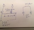
I have an 18v DC supply from 2, 9v batteries hooked in series. Their output measures 18.65v
I wired the 18.65v into 3, 500k resistors in series and ran a lead from the end of the 2nd resistor.
It measured 12.03v. Excellent says I.
So I take the 12.03v and keeping it as simple as I can, wire it to each end of A 1k resistor.
I figured that I would see a voltage drop of approximately 12v.
Nope, some very small reading like 003v.

What the heck am I not understanding. I thought that with only 1 simple component in the circuit that I would get 100% voltage drop.
My crude schematic is attached. Is this because I have the somewhat weird 12v, ie coming through the 3 resistors ?
And thanks.


FullSizeRender.jpg
 

dl324

Joined Mar 30, 2015
18,448
So I take the 12.03v and keeping it as simple as I can, wire it to each end of A 1k resistor.
I figured that I would see a voltage drop of approximately 12v.
Where is the schematic that shows how you had the 1k resistor connected? I see what appears to be the 3 500k resistors in series and a 390 ohm resistor connected to 12V.
Nope, some very small reading like 003v.
Where is the decimal point in your reading? Where are you placing the probes to take this reading, and what type of meter is it? Specifically, what is it's internal resistance.
 

wayneh

Joined Sep 9, 2010
18,134
What the heck am I not understanding.
That current is flowing, and that the tiny flow of current in the high-ohms resistors is hugely distorted when you add a low-ohms resistor. Use ohms law and you'll see that your results are entirely predictable.
 

dl324

Joined Mar 30, 2015
18,448
Is this because I have the somewhat weird 12v, ie coming through the 3 resistors ?
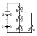
It's because you loaded your voltage divider.

upload_2017-10-13_12-25-16.png

The resistance of R2, R3, and R4 in parallel is less than 1k. R4 will drop about 1/501 of the voltage.
 

Thread Starter

Hextejas

Joined Sep 29, 2017
187
Where is the schematic that shows how you had the 1k resistor connected? I see what appears to be the 3 500k resistors in series and a 390 ohm resistor connected to 12V.
Where is the decimal point in your reading? Where are you placing the probes to take this reading, and what type of meter is it? Specifically, what is it's internal resistance.
I drew it wrong. The 330 is really 1k. It didnt make any difference, either 330 or 1k both yielded almost the same results.
and I placed the probe on either side of the 330 ohm resistor.
 

dl324

Joined Mar 30, 2015
18,448
what did you use to draw that schematic ?
The freeware version of Eagle. Using it won't magically make your schematics follow typical conventions. There are a number of ugly schematics posted on this site that were drawn using Eagle...

I print to PDF and post clips from there vs. posting ugly multi-colored screen shots.
 
Top