 Facebook
 Google
 GitHub
 Linkedin
Good morning,
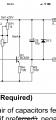
How would you interpret the connection of the base of Q1. Does this mean it’s not connected or that the base is connected to R5 and whatever else on the other side? Since it’s not my circuit, I can’t display the entire drawing.
How would you interpret the connection of the base of Q1. Does this mean it’s not connected or that the base is connected to R5 and whatever else on the other side? Since it’s not my circuit, I can’t display the entire drawing.
Attachments
-
 262.7 KB Views: 66


