Thevenin equivalent of two-ports network

Thread Starter

YoGMan

Joined Sep 20, 2017
76
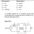
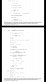
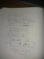
Hello friends , I'm asked the question below and I have the answer from the answer booklet(please zoom the picture) but I would like to know what is going wrong in my workings as i am getting R th= 50k ohm ,not 42k Ohm as in the booklet.Please
 

Attachments

The Electrician

Joined Oct 9, 2007
2,986
Hello friends , I'm asked the question below and I have the answer from the answer booklet(please zoom the picture) but I would like to know what is going wrong in my workings as i am getting R th= 50k ohm ,not 42k Ohm as in the booklet.Please
The answer booklet derives the h parameters of the two port and proceeds from there. Why are you deriving the Z parameters, and working from there? Were you instructed to use the Z parameters? You should, of course, get the same answer.

You have your derivation like this:

Mat1.png

But it's conventional to format like this:

Mat2.png

See the discussion of impedance parameters at: https://en.wikipedia.org/wiki/Two-port_network

Using the conventional format, you have z11=1000, z12=5, z21=2000000 and z22 = 50000.

The mistake you are making is assuming that the output impedance of a two port defined in terms of its Z parameters is just z22 when there is a source impedance driving the input.

What you need to do is to consider the properties of a terminated two port. You need the output impedance of your two port with a finite source impedance connected to the input port.

Have a look near the bottom of the referenced Wikipedia page under the heading "Collapsing a two-port to a one port". The example there calculated the input impedance with a load impedance connected. You need to do the same sort of calculation with a source impedance connected to find the output impedance. That will be your Thevenin impedance.
 

Thread Starter

YoGMan

Joined Sep 20, 2017
76
The answer booklet derives the h parameters of the two port and proceeds from there. Why are you deriving the Z parameters, and working from there? Were you instructed to use the Z parameters? You should, of course, get the same answer.

You have your derivation like this:

View attachment 140132

But it's conventional to format like this:

View attachment 140134

See the discussion of impedance parameters at: https://en.wikipedia.org/wiki/Two-port_network

Using the conventional format, you have z11=1000, z12=5, z21=2000000 and z22 = 50000.

The mistake you are making is assuming that the output impedance of a two port defined in terms of its Z parameters is just z22 when there is a source impedance driving the input.

What you need to do is to consider the properties of a terminated two port. You need the output impedance of your two port with a finite source impedance connected to the input port.

Have a look near the bottom of the referenced Wikipedia page under the heading "Collapsing a two-port to a one port". The example there calculated the input impedance with a load impedance connected. You need to do the same sort of calculation with a source impedance connected to find the output impedance. That will be your Thevenin impedance.
Thanks friend , I was making the same mistake- I needed to short circuit to get the short circuit current , the 50k ohm is not the thevenin resistance .Thanks again ;)
 

MrAl

Joined Jun 17, 2014
13,728
Hello friends , I'm asked the question below and I have the answer from the answer booklet(please zoom the picture) but I would like to know what is going wrong in my workings as i am getting R th= 50k ohm ,not 42k Ohm as in the booklet.Please
Quick question:

The first diagram shows a measurement of i2=-200ma but V2=0. That's impossible isnt it?
Is it really true that i2 is really internal to the network? That would make sense but the drawing should be changed then.
That way if the output is shorted, i2 can still flow out of say the top node and into the bottom node. Stated another way, V2 can only be zero when Ro is made equal to zero.
 

The Electrician

Joined Oct 9, 2007
2,986
Quick question:

The first diagram shows a measurement of i2=-200ma but V2=0. That's impossible isnt it?
Is it really true that i2 is really internal to the network? That would make sense but the drawing should be changed then.
That way if the output is shorted, i2 can still flow out of say the top node and into the bottom node. Stated another way, V2 can only be zero when Ro is made equal to zero.
Note that measurement 1 has V2 = 0, and measurement 2 has I2 = 0. In other words, the first one is an output shorted measurement, the second is an output open measurement. Also, note that the solution from the answer booklet derived the h parameters. Those parameters are:

h11 = 800
h12 = 1/10000
h21 = -40
h22 = 1/50000

These are typical for a transistor. V2 can be zero even if Ro is not zero--just apply a short to port 2.
 

WBahn

Joined Mar 31, 2012
32,979
Hello friends , I'm asked the question below and I have the answer from the answer booklet(please zoom the picture) but I would like to know what is going wrong in my workings as i am getting R th= 50k ohm ,not 42k Ohm as in the booklet.Please
I know you've solved the problem, so this is more of a general observation for the future.

Since you have the author's solution manual, you have the chance to really leverage it to help your learning. The fact that you didn't just copy the author's work and turn it in says that you want to learn -- which puts you way ahead of most folks.

So the question is how can you effectively use such a resource?

Once you recognize that you don't have the same result that the author has, don't just go asking for others to walk through your work and point out where you went wrong.

Instead, work through the author's solution (which may be a very different approach than you took) and be sure that you understand (and agree with) each step they took. If, at some point, you can't make the connection between one step and the next, bang away at it for a while and THEN seek assistance in understanding THAT step and nothing more. Make your question specific to THAT step. Then proceed (and repeat as necessary).

While doing this, see if something pops up that gives you insight into what you might have done wrong in your approach. It often will, even when the approaches are quite dissimilar.

Of course, always keep in mind that the author's solution may have errors -- I would not be surprised to discover that there has never been a single solutions manual ever printed that didn't.

Finally -- and this really is critical much of the time -- once you believe you understand the solution provided, take out a clean sheet of paper (preferably the next day) and rework the problem from scratch without ANY reference to the solution. You will be surprised how often the author's solution only seemed to make sense to you as long as you had THEIR work in front of you to refer to. Humans are actually quite bad at distinguishing what we understand because we KNOW it from what we understand because we can RECOGNIZE it when we see it.
 

MrAl

Joined Jun 17, 2014
13,728
Note that measurement 1 has V2 = 0, and measurement 2 has I2 = 0. In other words, the first one is an output shorted measurement, the second is an output open measurement. Also, note that the solution from the answer booklet derived the h parameters. Those parameters are:

h11 = 800
h12 = 1/10000
h21 = -40
h22 = 1/50000

These are typical for a transistor. V2 can be zero even if Ro is not zero--just apply a short to port 2.

HI,

Yes i am aware of how the h params are found, but that's not what the graphic is showing really and so this can be deceiving.

Look at the schematic. Draw a line directly through the symbol "V2" to short it out. Now show that the current, where it is drawn, can equal -200ma.

In other words, the current I2 is shown as flowing through Ro when that's not the way this is done. The current I2 should be shown flowing through V2 not Ro, so where it is drawn now is deceiving if not outright incorrect.

Now move the symbol for "I2" and associated arrow to *inside* the box so that it is between the big dot and the plus sign for V2. Now when V2 is shorted the current I2 can be anything, although the first measurement given is -200ma in that case, and that is then correct.

So the problem i found is really with the graphic itself, not with finding h params.
 

The Electrician

Joined Oct 9, 2007
2,986
HI,

Yes i am aware of how the h params are found, but that's not what the graphic is showing really and so this can be deceiving.

Look at the schematic. Draw a line directly through the symbol "V2" to short it out. Now show that the current, where it is drawn, can equal -200ma.

In other words, the current I2 is shown as flowing through Ro when that's not the way this is done. The current I2 should be shown flowing through V2 not Ro, so where it is drawn now is deceiving if not outright incorrect.

Now move the symbol for "I2" and associated arrow to *inside* the box so that it is between the big dot and the plus sign for V2. Now when V2 is shorted the current I2 can be anything, although the first measurement given is -200ma in that case, and that is then correct.

So the problem i found is really with the graphic itself, not with finding h params.
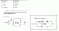
I think the two "measurements" were made on just the two port network (I1 got cut off in this image):

Network.jpg
 

MrAl

Joined Jun 17, 2014
13,728
I think the two "measurements" were made on just the two port network (I1 got cut off in this image):

View attachment 140279
Hi,

Yes, and notice you have to change the schematic to show this. That was my point.
I would bet that someone copied it and just drew the resistor.

In the attached diagram i show the modified schematic which is valid no matter how we read the text.
 

Attachments

WBahn

Joined Mar 31, 2012
32,979
What is the basis for claiming that the current in a wire inside the edge of a drawn box is somehow different than the current in that same wire outside the edge of a drawn box?

In both cases, the currents are those entering the top terminal of the associated port.
 
Hi,

Yes, and notice you have to change the schematic to show this.
Not if you don't make the false assumption that the schematic shows the conditions under which Measurement 1 and Measurement 2 were made. Measurements 1 and 2 tell us what's inside the box insofar as its terminal properties go. Those measurements weren't made with any load resistor on the output at all; only with a short and an open. If a person weren't sure about that they could tell by following the working in the answer booklet.
 
Last edited:
The problem could just as well have not given any measurements at all, and just said:

"You are given a two port with the following h parameters.
h11 = 800
h12 = 1/10000
h21 = -40
h22 = 1/50000

Now if the two port is driven from a 250 ohm source, what load resistance Ro will result in maximum power transfer to Ro?"
 

WBahn

Joined Mar 31, 2012
32,979
One thing that I hadn't noted before. The problem diagram explicitly states that the two-port network is a resistive network. That being the case, how can 4 V and 5 mA at one port produce a short-circuit current of -200 mA at the other port? I had previously assumed that there was a dependent source in the box.
 

WBahn

Joined Mar 31, 2012
32,979
So I decided to work the problem and my take is a bit different than either the TS's or the author's.

My goal was to make getting the two-port network parameters trivially easy. Given the two measurements provided, in one case V2 is zero and in the other case I2 is zero, so I decided to make these two variables my independent variables. Thus I have

\(
V_1 \; = \; AV_2 \; + \; BI_2
I_1 \; = \; CV_2 \; + \; DI_2
\)

I don't know if this set of parameters has a name or not and, if so, what letter is used. I just used {A,B,C,D} arbitrarily.

Applying the first measurement:

\(
4 \, V \; = \; B(-200 \, mA)
5 \, mA \; = \; D(-200 \, mA)
\)

So

\(
B \; = \; \frac{4 \, V}{-200 \, mA} \; = \; -20 \, \Omega
D \; = \; \frac{5 \, mA}{-200 \, mA} \; = \; - \frac{1}{40}
\)

Applying the second measurement:

\(
20 \, mV \; = \; A(40 \, V)
20 \, \mu A \; = \; C(40 \, V)
\)

So

\(
A \; = \; \frac{20 \, mV}{40 \, V} \; = \; \frac{1}{2000}
C \; = \; \frac{20 \, \mu A}{40 \, V} \; = \; \frac{1}{2 \, M \Omega}
\)

To find the Thevenin resistance of the circuit in the problem, I'll call the 250 Ω source resistance Rs and will zero (turn off) the 5.25 mV source. This means that

\(
V_1 \; = \; -I_1 R_s
\)

Therefore we have

\(
-I_1 R_s \; = \; AV_2 \; + \; BI_2
I_1 \; = \; CV_2 \; + \; DI_2
\)

Multiplying both sides of the bottom equation by Rs, we have

\(
-I_1 R_s \; = \; AV_2 \; + \; BI_2
I_1 R_s \; = \; C R_s V_2 \; + \; D R_s I_2
\)

Adding, we get

\(
0 \; = \; AV_2 \; + \; BI_2 \; + \; C R_s V_2 \; + \; D R_s I_2
\( A \; + \; C R_s \) V_2 \; = \; -\( B \; + \; D R_s \) I_2
\)

The Thevenin resistance is simply the ratio of V2 to I2:

\(
R_{th} \; = \; \frac{V_2}{I_2}
R_{th} \; = \; - \frac{B \; + \; D R_s}{A \; + \; C R_s}
\)

Since the load resistance needs to match the Thevenin resistance to achieve maximum power transfer, we now have everything we need find the load.

\(
R_0 \; = \; R_{th}
R_0 \; = \; - \frac{B \; + \; D R_s}{A \; + \; C R_s}
R_0 \; = \; - \frac{\(-20 \, \Omega \) \; + \; \( - \frac{1}{40} \) \( 250 \, \Omega \)}{\( \frac{1}{2000} \) \; + \; \( \frac{1}{2 \, M \Omega} \) \( 250 \, \Omega \)}
\)

Multiplying top and bottom by 2000 yields

\(
R_0 \; = \; \frac{40 \, k\Omega \; + \; 12.5 \, k\Omega }{1 \; + \; 0.125}
R_0 \; = \; \frac{52.5}{1.25} \, k\Omega
\;
R_0 \; = \; 42.0 \, k\Omega
\)

Take note of how the units are tracked properly throughout the work.
 
I don't know if this set of parameters has a name or not and, if so, what letter is used. I just used {A,B,C,D} arbitrarily.
They are in fact the ABCD parameters, except the usual convention is to define them as:

\(
V_1 \; = \; AV_2 \; - \; BI_2
I_1 \; = \; CV_2 \; - \; DI_2
\)

thus taking I2 as a current leaving the two-port so cascaded two-ports defined in this way can give an overall 2x2 ABCD matrix by just multiplying the individual ABCD matrices.

https://en.wikipedia.org/wiki/Two-port_network
 

WBahn

Joined Mar 31, 2012
32,979
They are in fact the ABCD parameters, except the usual convention is to define them as:

\(
V_1 \; = \; AV_2 \; - \; BI_2
I_1 \; = \; CV_2 \; - \; DI_2
\)

https://en.wikipedia.org/wiki/Two-port_network
The negative sign makes sense given that B and D, as I defined them, would usually be negative.

If I had had to guess, I would have thought that I2 and V2 in terms of I1 and V1 would have been called the transmission parameters.

Ah, I see that the reason it is defined this way is because of the way the matrices can be cascaded since matrix multiplication isn't commutative.
 

MrAl

Joined Jun 17, 2014
13,728
What is the basis for claiming that the current in a wire inside the edge of a drawn box is somehow different than the current in that same wire outside the edge of a drawn box?

In both cases, the currents are those entering the top terminal of the associated port.
Hi,

The thing i did not like was that they had shown the current arrow as being the current through the resistor Ro, so if you short V2 then I2 must equal zero. This led me to believe that the schematic was a little deceiving.

Electrician believes it is a false assumption that the circuit is the circuit used to measure the h params, and i do agree to that, but the circuit should not show I2 where it is at that point because V2 could be a voltage source and in that case I2 could be different than the actual current into the port 2 of the two port network. Note that in order for him to explain his position he had to redraw the network too.

I will say though that as long as anyone doing this is aware of that fact, it wont matter as much so i wont debate it any more as i dont think it is necessary here. I just thought it would be confusing for people just learning about this stuff because I2 is not the two port I2 really.
 

MrAl

Joined Jun 17, 2014
13,728
Not if you don't make the false assumption that the schematic shows the conditions under which Measurement 1 and Measurement 2 were made. Measurements 1 and 2 tell us what's inside the box insofar as its terminal properties go. Those measurements weren't made with any load resistor on the output at all; only with a short and an open. If a person weren't sure about that they could tell by following the working in the answer booklet.
Hi,

Well that is actually part of my argument. In short, if we had a better drawing there could be no false assumption.
Yes if you follow the worked example you can figure it out, but then we are still a little at odds with the schematic itself which shows I2 AFTER V2 instead of before it where it is always drawn in text books.

It's your choice of course how you want to interpret the schematic and text. I believe it would be clearer to show a better schematic as i did in one of my posts for reference.
 
Top