The TIP42 in bridged class ab amp is hot.

Audioguru again

Joined Oct 21, 2019
6,826
You lost me at the 1.41W.
I had current values in the 500-600mA at max peak and multiplying that by 4.5 doesn't give me 1.41W. What current value are you use and from where to get 1.41W?
Amplifiers are not spec'd using peak voltage and peak current but cheating salesmen do.
Convert peak-to-peak to RMS on a sinewave by dividing the p-p voltage by (2 times the root of 2).
1) The root of 2 is 1.414.
2) There is an amplifier on each end of the speaker (bridged) then the 4.5Vp-p x 2= 9Vp-p across the speaker.
3) 2 times 1.414 is 2.828. Then 9Vp-p/2.828 is 3.183V RMS.
3) Power is RMS voltage squared divided by the speaker impedance. Then 3.183V squared is 10.13.
4) The power in the 7.2 ohm speaker is 10.13/7.2= 1.41W.

The peak voltage on the 7.2 ohm speaker is 4.5V. The peak current is 4.5V /7.2 ohms= 625mA.
The RMS current is 625mA divided by (the root of 2)= 442mA RMS.
The RMS voltage was 3.183V.
Then the power is 442mA x 3.183V= 1.41W
 

Thread Starter

mike_canada

Joined Feb 21, 2020
239
I think audioguru should invent some online calculators for this site for people to use. It's a lot of math to digest but I think I could work it out
 

Audioguru again

Joined Oct 21, 2019
6,826
Mike, most of us have not designed a power amplifier like yours for many years.
Now we use a power amplifier IC where the math and graphs show everything about it.
It has many transistors inside it so that no fiddling with resistors is necessary.
 

Thread Starter

mike_canada

Joined Feb 21, 2020
239
ww.png

Ok so I changed a few parts to match the resistors I own and I'm curious if I did all my math right or not. Both of my equations suggest I probably don't need a heatsink on any transistor. I'm trying to get the best "bang" (rhythm) for my buck.
 

Audioguru again

Joined Oct 21, 2019
6,826
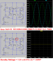
Yes, your amplifier produces only 1.736W when the input level is turned down to avoid bottom clipping. If it is biased properly for symmetrical top and bottom clipping then the max undistorted output power will be more.

Before we talked about standby wattage caused by only the output stage idle current. But the current of the driver transistor must be added plus any offset output voltage (maybe 0.5V difference?) between the amplifier output halves.

Resistors that you have? The transistors you have might have max or min specs then they will need completely different resistors that the simulation uses.

Here is "symmetrical clipping" biasing:
 

Attachments

Thread Starter

mike_canada

Joined Feb 21, 2020
239
But the current of the driver transistor must be added plus any offset output voltage (maybe 0.5V difference?) between the amplifier output halves.
So standby equals current taken at emitter from both power transistors times (Vcc + 1 (0.5 for each vbe voltage value))? I'm kinda confused.
I'm not an expert on audio math.

Resistors that you have?
It means actual resistors I currently own. I own lots of 1K, 2K, 10K, 22K, 56K, 82K, 100K, 120K, 160K, 560K, very few of 33K, 4.7K and if I'm lucky, up to 3 resistors of other values mentioned in this thread. And all resistor values are 1/4 watt but I have very few that are 1/2 watt and 1 watt.
 

Audioguru again

Joined Oct 21, 2019
6,826
The idle current of the driver transistor is calculated by the voltage across its collector resistors.
The output offset voltage between the bridged amplifier halves is probably high because the separate transistors are not matched like in a simulation or in an amplifier IC.
 

Thread Starter

mike_canada

Joined Feb 21, 2020
239
I just found a way spice can give me a hand. I just have to move my cursor over the transistor and spice will tell me how much power it dissipates. Then again, maybe I should include 5% tolerance to its values since its not perfect.
 

Thread Starter

mike_canada

Joined Feb 21, 2020
239
Ok now this is crazy. I decided to replace the diodes. I had tons of 1N4001's and very few 1N4007's. So I go and replace the 1N914's with 1N4001's and the circuit improved somewhat because it takes a little longer to reach oven temperatures on the transistors but after replacing the diodes, when I looked at spice, its telling me that using 1N4007's would cause less power consumption. I don't get why... And even if the power dissipation plus audioguru's tolerance levels equal 1.75-ish watts, I don't understand why the transistors would heat up and as for audio, the volume is almost at bare minimum. Battery source was 7.2V newly charged when the heating started, but with the 4 AA batteries, I didn't really notice heat.
 

Thread Starter

mike_canada

Joined Feb 21, 2020
239
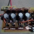
IMG_20221010_223729.jpgtheres the meat of my audio amp close up. So far I used 14AWG copper wire as heatsinks but I may have to double the thickness.
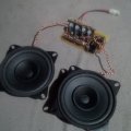
Also, I have the speakers connected on 10cm wire.
IMG_20221010_223737.jpg

the voltmeter id measure the 7.2V battery at 7.8V but when I was testing things, I noticed the heat was slowly incrementing on the transistors over a period of 45-60 seconds. then towards the end of that time, I kinda smelled something but idk if it was the solder gunk under the circuit board that was causing odours because the circuit board was warm too, but it wasn't oven hot like before so it seems the diode change is a step in the right direction.
 

Ian0

Joined Aug 7, 2020
13,230
, I noticed the heat was slowly incrementing on the transistors over a period of 45-60 seconds.
You have a thermal runaway problem. As the transistors heat up Vbe decreases. The diode voltage stays the same. The difference between Vdiode and Vbe sets the bias. As Vbe decreases the bias increases, which causes the transistors to heat up some more
 

Thread Starter

mike_canada

Joined Feb 21, 2020
239
I also wondered if my choice of coupling caps are wrong. In all my tests, the coupling caps were 1 0.1uF ceramic and 1 22uF electrolytic.
I now replaced the 22uF with a 2200uF to hopefully cancel out voltage fluctuations from the supply. I guess after that I have no choice but to increase resistor values.
 

Thread Starter

mike_canada

Joined Feb 21, 2020
239
I should probably add resistors from the 2N2222's bases to ground because transistors have a thing called "leakage current" and I'm thinking maybe I let that also get out of hand which might be another factor of thermal runaway.
 

Martin_R

Joined Aug 28, 2019
137
The diodes need to be in physical contact with the output transistors for them to do their job of thermal compensation. At the moment the transistors are getting hot, meaning the base - emitter voltage goes down, the net result is the transistor base current increases, so therefore does the collector current, therefore it gets hotter!
The diodes need to thermally track this, by either in physical contact with the transistors or heatsink. As the diodes then heat up their forward voltage drops too, compensating for the transistors.
 

Ian0

Joined Aug 7, 2020
13,230
I should probably add resistors from the 2N2222's bases to ground because transistors have a thing called "leakage current" and I'm thinking maybe I let that also get out of hand which might be another factor of thermal runaway.
Leakage current rarely causes problems with silicon transistors in properly designed circuits.
 

Ian0

Joined Aug 7, 2020
13,230
The diodes need to be in physical contact with the output transistors for them to do their job of thermal compensation. At the moment the transistors are getting hot, meaning the base - emitter voltage goes down, the net result is the transistor base current increases, so therefore does the collector current, therefore it gets hotter!
The diodes need to thermally track this, by either in physical contact with the transistors or heatsink. As the diodes then heat up their forward voltage drops too, compensating for the transistors.
That’s the reason I suggested replacing the diodes with diode-connected transistors of the same type as the output transistors.
 

MrChips

Joined Oct 2, 2009
35,033
I said it once, I said it twice, I said it multiple times. This chap is going about it all wrong and I have offered to help but he ignores me.
Why do you experts continue to help this poor sod who continues down the wrong path?
 

Martin_R

Joined Aug 28, 2019
137
MrChips, you are indeed correct. You have to admire the enthusiasm that Mike has for continuing a project that isn't optimal and certainly not battery friendly.
I would look to having a voltage boost circuit to obtain say, 12v from the battery and use an off the shelf amplifier ic. Forget about the bridging amp, or just use class D and get good battery life.
Present design is 'good' to learn with (you learn by your mistakes, they say), but has so many limitations. I know the help supplied has been tremendous on this thread, and I sincerely hope that Mike has learned something along the way .
 
Top