Tesla Coil! First real setup need some help

Thread Starter

nissan20det

Joined Apr 3, 2015
69
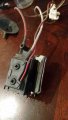
Hey guys so Ill post some pics up soon of what I got going so far. My first coil was a 24VDC SSTC and I got it to work first go! I got so stoked that it worked I decided to build a SGTC. This coil is a little over a foot tall nothing crazy im about three weeks in. I am having troubles finding equations or even how to figure a couple parts out. My power supply is some kind of flyback coil a friend sold me for a car flame kit. LOL that worked awesome! I could somewhat test the output with my DS202 and a fluke hv probe. I got around 30Kv AC. So I know I need to rectify, thats taken care of but how do i calculate what my capacitance should be? I couldn't find the equation for it, I'm sure youll need to know your output current. So how do I figure that out on a random flyback? I made some HV caps, I have about 31.58nf good to 40kv.I wanna make sure thats not too much.

My next big stump is the Choke. How do I calculate that? What value resistance should it be? I cant find that anywhere, just people showing pics and saying here's my choke.

lastly I just wanted to pic someones mind on synchronous rotary spark gap. I have a good stepper motor setup i can use and wanted to know what kind of equipment is needed to get in sync with your mains freq.

Thanks in advance guys!!!
 
This website is absolutely fantastic when it comes to SGTC equations. I would specifically check out the DC Tesla Coil section, with special attention to the dc resonant charging section. It will tell you how to calculate your tank capacitor value, and inductance of your choke. I am (slowly) working on a DC coil as well, with asynchronous spark gap (no difference between async and sync with DC supply), albeit a 16kW version. http://www.richieburnett.co.uk/tesla.s
 

Thread Starter

nissan20det

Joined Apr 3, 2015
69
okay cool well maybe u can help me. I did read that site a wile ago but didnt see it has other pages. I was looking at all that and just got lost on what to start with. but so say im using a type of unknown 12v dc flyback, Is there even a way to calculate my needed capacitance? I also just wanna test this thing. if i just do this coil on a 12v DC wall adapter to my 12v flyback one diode out with cap from diode to ground and spark gap after diode as well going to primary should this work? also would there be any benifit to using 12ac instead of dc? just like this but minus the 555 since mine already oscillates, and output being to primary......---->

DC Tesla coil.gif
 
The way you are talking about setting it up should work yes. I don't believe you could use 12VAC to power a flyback, and even so there wouldn't be a benefit if you could. You said you were considering a rotary spark gap. Will you be using one on this coil or just a static gap? For a static gap (which will be the easiest for your supply) you shouldn't need a choke. One thing that would be very helpful to know would be how many amps your flyback setup draws at 12VDC when it is just arcing so we can calculate power (watts). Another thing that while less important is good to know is the frequency the flyback oscillates at. Once you have have the flyback's power, it will be much easier to determine the value for your tank capacitor.
 

Thread Starter

nissan20det

Joined Apr 3, 2015
69
Okay well it's ment to be powered by 12vdc. It's like a car ignition coil but it's for a flame kit, you don't need a switching device to make it oscillate.(like a 555 or relay and cap) You apply 12v and it arcs to input ground. If I have arc to far, say more then 1.5inch I hear it internally arc. It's meant to just hold a steady Arc in your exhaust to ignite leftover fuel. It pulls about .563 amp at 12 volts so about 6.4 watt. I was going to see how it did with a 12-volt input and then possibly try 24v.

And yes for this setup I would just be trying a static Gap to get it going. I couldn't really test of the output of this very well. I only have a 6kv fluke probe and a ds202 scope. Technically that probe is a times thousand probe and the scope can do up +/-40volts/80vpp so I figured it would probably be ok to test so I tried and it looks about 30kv with a 9v but I was too scared of frying my scope to really go long enough to get a frequency reading.
 

Thread Starter

nissan20det

Joined Apr 3, 2015
69
Okay this is what I have going on. This is just my small one I was going to test with this setup. For some reason it seems like I'm losing a lot of power after each diode. Before the first diode I can get an inch and a half Spark. After the first diode I get about a quarter inch Spark and after the second less than 1/16. I have two 20 KV 30 Ma diodes in series for 40kv. My power supply was a 12 volt AC 500ma wall adapter that I Bridge rectified and have 156 microfarad to filter 12v rail. Am I doing something wrong or does this just not output enough power?
 

Attachments

What is that green wire connected to the same terminal of the spark gap as the red wire? Also you said you had made some HV caps, are those out of frame or not hooked up? To be quite honest, I could see something like this having 6W in losses alone. I would suggest using a 12V oil burner ignition module. They are rated at 20kV at 30mA output , which is definitely BS as that is 600W. They are also rated at 12V at 5A input, which is 60W. They actually do pull about 5A at 12V, so they are actually around 60W (probably around 50W output after losses in switching). Either way about 10X the grunt of your supply. They are flyback based, and the only thing you have to keep an eye on is keeping the heat sink cool, since they are meant to sit in the burner blower's air stream. Failure to cool them will result in prompt popping. I have a number of them, and would be happy to send you a couple if you want to dm me.
 

Thread Starter

nissan20det

Joined Apr 3, 2015
69
Ya you can see one cap in there. It's on the top left. Is rolled up transparency sheets with foil inside. They should each be good to 40kv and they read about 6.8nf I have 5 total. that's also what the green wire is. It connects my caps to HV side after diodes. Other end of cap is grounded. Seems like they work cuz as I add them the spark pops louder and louder. But ya man I would freaking love it if you could send me some of those. What do you mean by dm you?
 
I guess there isn't a way to directly message other users on here, but I started a conversation with you. Seems to be the same thing. I just don't want to ask for your shipping address where everyone can see it.
 

Thread Starter

nissan20det

Joined Apr 3, 2015
69
Sweet man ya I thought that's what you ment. So I was ganna start this other supply idea today just for sh**s and gigs. But it's a supper old fly back. Like from 60s early 70s. So it's none rectified I'm sure. But I see alot of success with driving them with a ballast. So i have it all wired up and was ganna test it today. My question on this on is do I need to rectify it?

I'm so confused cuz I was on some forum about flybacks for TC's and this guy said they have to be a DC out or you need to rectify. I'm confused because that link you sent me has two completely separate setups for DC or AC. So is seems to me you can do a tc on a fly back without rectifying right? Out of these two pictures what tells you out of your equipment which circuit to use? On a none interally rectified flyback the only thing making it a HV DC supply is using diodes. When do you know the cap must be in series instead of in parallel?

circuit.gif

dcdeq1.gif
 
You will definitely want to rectify. That AC setup is meant to be run at mains frequency, and I suspect things would get quite funny if you tried it at flyback frequencies. If using mains frequency AC the cap is in series, if DC the cap is in parallel.
 

Thread Starter

nissan20det

Joined Apr 3, 2015
69
Okay cool. Well I just tore this out of a TV today. My super old one was fried. So one how do u tell if your fly back is internally rectified. And what do I do with these other wires? There's a thick white and small red out of the side that say screen(small red) and focus(big white). Will these have power when I run this? I know to use the main big red that had suction cup but I've never seen 3 different HV wire out of one flybacks.
 

Attachments

I'm not quite sure how to tell if your flyback is internally rectified, maybe someone else can chime in on this? The focus wire may be at a modest voltage (few hundred probably), and the screen wire is likely at a moderately high voltage (few thousand). You should just be able to cap them off and not worry about them.
 

Thread Starter

nissan20det

Joined Apr 3, 2015
69
Okay cool. There also a screw on each extra wire. Could they be adjustments? Maybe see if the arc and turn screw to see if it arcs less? Or u say if it's lower I can try to use my fluke probe. But ya u think there adjustments?

Also if powering this flybacks with a ballast will I be okay with using some 20kv diodes in parallel? Would 40kv be okay or when using a ballast do u get higher voltages?
 
They are indeed adjustment screws, however they adjust the voltage on the screen and focus wires, not your HV output. I would go with 60kV if you can for diodes. One thing to note is that driving a flyback is quite rough on a ballast. When I switched from CFLs to LEDs in my house I had a good time popping each CFL ballast by using it to drive a flyback. If you get a really beefy ballast you should be ok.
 

Thread Starter

nissan20det

Joined Apr 3, 2015
69
Ya that's what I heard about the CFL ballasts. I'm talking about the big bar ones. Everyone I have seen using those say they don't even get warm. But I guess will see.

I attached the new tv flybacks schematic that I'm using. Funny how all the you tube videos say find the pair of pins next to each other that reads one ohm. This fly backs primary is pin 1 and 5. But look at the pic. Does that mean theres internal diodes? Also what do you think the voltage rating is of the internal diodes?

I have 8 20kv 30ma diodes. When using a ballast you think I'll be okay running just 3 in series at output for 60kv + internal? Also do I need to full wave rectify? And is 30ma plenty? Should I run any in parallel?

One weird side note. I got my 12v flyback to work. Got 2in Sparks off top load. I tried to fully rectify and found I needed to reverse the diodes. Why is the anode more attracted to ground? It's like it's outputting a negitive voltage.

mxDh6BM.gif
 
Yes, those are indeed internal diodes, and your flyback is internally rectified. It's hard to guess the voltage rating of the internal diodes, but I'd imagine they can handle whatever the flyback can throw at it.That being said, you will not need to use any external diodes. The HV lead on your flyback is a positive voltage. On your 12V flyback, the anode is outputting a negative voltage, as all anodes do. Electrons flow from the cathode to the anode, building up electrons on the anode thus making it negative. The cathode accepts electrons and emits them, thus being positive.
 

Thread Starter

nissan20det

Joined Apr 3, 2015
69
Ahhhh lol kk I see sweet. Okay well hat you mean by what ever I can throw at it does that mean I shouldn't even worry about the diode using a ballast?. Them being internal if I use a ballast at 600-900v to the primary. Won't that be between 60kv-100kv? I just figured I may pop a internal diode. And being internal that mean this will be a paper wieght. You think it'll be okay in ur opinion. Do t give two sh**s about the ballast just the fly back.

Also my caps are 3sheets of transparency-foil-3-foil I figure good to 40kv should I run two in parallel? Think that'll be okay?
 
Last edited:
Allow me to rephrase. By "whatever the flyback can throw at it" I meant under normal operating conditions, which if I recall correctly is about 700V to the primary. The turns ratio isn't actually that high, and the output is fed to an integral tripler.
 

Thread Starter

nissan20det

Joined Apr 3, 2015
69
Okay so would it help to add a 20kv diode at the hv end to ad 20kv to all of them? What would you do in my situation here I'm just nervous cuz I'd like to use this flybacks no fry it. And for some reason I can't get my zvp driver to work. All I have is a labtop charger at 20v 4.5 amp. But I can't get the circuit to work. So if u think the ballast is a gamble do you know of a simple driver that works? I have wired parts from fixing amps but I have some beefy MOS and bjts. 2xIRFP450,14xIXTQ50N25, 12xNJW2194 and 12x2193. Only 555's I have are surface mount. I did this circuit and couldn't get it to work. I had everything but there fast diodes so I used 1N4937G is all I had different. WTF..but these at low primary voltages put out lower HV right? I'm okay with like 6-10kv to start. Using this 6watt 12v flyback to a 1amp 800v ballast driven flyback seems to me like a massive jump.

maxresdefault.jpg
 
Top