Temperature sensor with LM393 Comparator and NTC Thermistor

Thread Starter

q12x

Joined Sep 25, 2015
2,227
I guess you are ignoring my posts. That is ok. I am not offended.
I posted a solution in post #108. If you use a 5 V supply, the outputs are in 0.5 V steps.
30 °C = 1.5 V
40 °C = 2.0 V
50 °C = 2.5 V
60 °C = 3.0 V
Now connect this to an LM3914N, trim the range and offset, and you're done!
Im not ignoring anyone. But I didn't understood your post. That scale from that graph shows 0V to 0.7V. Not from 1.5V to 3V as you say here. And Im prioritizing, and probably at that time I was thinking on something else what to do. Sorry about not testing your ideas. But I only have 2 hands and a certain amount of time and concentration. You must understand that. Is good that you point me towards your solution.
- So you say,, to test this cct:
1725156506470.png
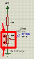
- You made me wonder for a few minutes why didnt I use this simple cct in the first place? But I did. You just copied what I did in the very first post. Take a look in my #1 post and you'll see this exact cct. That cct is using "your cct" linked directly to comparator imput and I actually got the best results from it, now in retrospect, but with a very big shifting problem that bugged me from the very beginning. Now, after all this time and experiments and 3 circuits, I start to kind of see where the problem really is. And Im suspecting my LM393 for low sensitivity. I have to test it yet, for now is a suspicion.
Here: 1725157841887.pngOnly that you are using a battery and Im using an aligator clip from my 5V PSU. And different values for components.
But its the same idea. Also I build this not only here in simulator, but in reality too with relatively interconnected results. I started to make a "full" circuit based on this circuit idea already comprised of 2 ICs, so 4 comparators, for 30,40,50,60*C steps. But with the knowledge they will have that serious error Im mentioning all the time, "the shifting problem". It remains the only one that works. Funny, isn't it?
 
Last edited:

dl324

Joined Mar 30, 2015
18,405
mister dl324 helped very well, with his last cct using that ladder of series 10k resistors, the change was 100mV instead of 10mV.
You always had the option of amplifying the voltage from the thermistor to get a larger voltage to resolve. It would have never occurred to me to not amplify the voltage from the transistor junction.
partticularely this LM393 which all of you jumped like kindergarden children, "yaaaaaaah, its the best" but in my experience, its completly crapanolly. To be fair, Im using them for the first time with this project, and of course its my first impression playing its role, but so far they failed me royally. Im starting to get tired of them.
LM393 are fine for your application. As with any tool, you just need to know how to use them properly.

If Proteus can't handle LM393, just learn how comparators work, and you won't need a simulator. A comparator just compares voltages at its inputs (it's not a digital comparator, there logic comparators for comparing digital signals, but LM393 has analog inputs). It can be used as a slow opamp; just as opamps can be used as slow comparators.

When the difference between the non-inverting and inverting inputs is positive, the output will be HIGH. When the difference is negative, the output will be LOW. When the inputs are the same, it will probably oscillate. To avoid that, we add hysteresis.

Based on my learnings about the thermal coefficient for a transistor junction, I've modified my circuits to use a current close to 1mA. At that current, the thermal coefficient is 2.2mV/°C. At 50uA, it was more like 2.4mV. I also cherry-picked resistors to get the amplification of both opamps to be closer to 10.

At first I was using the junction voltage at room temperature to determine temperature. After using a water bath for some earlier measurements, I decided to use the junction voltage at 0°C for calibration. I also measured a dozen transistors and sorted them by junction voltage.

I was trying to use my DVMs that can measure temperature, but I don't trust them. Can't use any of my infrared thermometers because I can't tell where it's taking the reading. I'll probably end up using my HP thermometer or use the resistor heating circuit to heat something large enough to use an infrared thermometer (after I check their accuracy).

I know the HP thermometer will be accurate. It uses a 2N2222A junction. AFAIK, those devices don't require calibration unless the junction is replaced.
 

MrChips

Joined Oct 2, 2009
34,954
Look at my circuit again. I showed a 1 V source. If you had read the text, I said use whatever source you want and just scale it up. So with a 5 V source, the steps are 0.5 V.

I did not copy your circuit. Your circuit does not give linear output. Look at the circuit values again. The series resistance is not the same value as the nominal resistance at 25 °C. This is very important. Use the resistance value at 50 °C, i.e. the halfway point between 30 °C and 70 °C.

I told you once, I told you twice. I don't know what you mean by shifting.

A 1 kΩ NTC thermistor is way too low. The themistor has to dissipate about 20 mW which results in self-heating. The resistance is going to drift lower and lower owing to positive feedback.

You need to place the thermistor in a controlled temperature environment. If you put it in water, water is an electrical conductor and will affect the measurement. You need a medium that is not electrically conductive.
 

Thread Starter

q12x

Joined Sep 25, 2015
2,227
To @dl324
Man, I know very well what a comparator is and do. Even if its a new component for me, I read all about it. I test it sufficiently to be very sure what it does. I might not know some very detailed or intimate problems about it, but I got already the general idea, like you try to explain it there. I didn't know about the hysteresis part, and you put me to read about it right now, but the rest is really a known subject to me. Nothing new. So its not a novelty for me anymore.
- Im using Proteus simulator for testing circuits and also for prototyping new ones. Its not because I dont know how a comparator behaves. Hahaha. You're silly.
To @MrChips
Ok, I have a question to you. What have you tried so far? Can you show me your circuit and your setup? How did you deal with yours? Did it worked as you explain here? Show me pictures from reality or your PC relevant to the practical experiment.
 

MrChips

Joined Oct 2, 2009
34,954
To @dl324
Man, I know very well what a comparator is and do. Even if its a new component for me, I read all about it. I test it sufficiently to be very sure what it does. I might not know some very detailed or intimate problems about it, but I got already the general idea, like you try to explain it there. I didn't know about the hysteresis part, and you put me to read about it right now, but the rest is really a known subject to me. Nothing new. So its not a novelty for me anymore.
- Im using Proteus simulator for testing circuits and also for prototyping new ones. Its not because I dont know how a comparator behaves. Hahaha. You're silly.
To @MrChips
Ok, I have a question to you. What have you tried so far? Can you show me your circuit and your setup? How did you deal with yours? Did it worked as you explain here? Show me pictures from reality or your PC relevant to the practical experiment.
Tell my why I should do your work for you after you ignore all my suggestions.
 

Thread Starter

q12x

Joined Sep 25, 2015
2,227
I was trying to use my DVMs that can measure temperature, but I don't trust them. Can't use any of my infrared thermometers because I can't tell where it's taking the reading. I'll probably end up using my HP thermometer or use the resistor heating circuit to heat something large enough to use an infrared thermometer (after I check their accuracy).
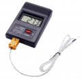
If you don't watch my movies ... I'm using this TM-902C-50C-to-1300C-Temperature-Meter-TM902C-Digital-K-Type-Thermometer-Sensor-Thermocouple-P...jpgdigital thermometer for a few years and is a great tool to have. Very reliable. And yes is a very cheap chinezium from aliexpress or ebay. But it worked flawlessly, I have only good words about it. It is great for component temp measurement, and Im talking from my experience, not my ass! I recommend you to get one if you permit monetarily, financially and capitalistically. hahaha. The only worry I have is that flimsy probe made from 2 wires twisted. I bought 10 more just to be sure. I bought them initially for experimentation purposes, but as spares too. 2 rabits with 1 shot. Right? They are still on the road to come.
1725161289734.png
 
Last edited:

Thread Starter

q12x

Joined Sep 25, 2015
2,227
Tell my why I should do your work for you after you ignore all my suggestions.
Its not about that.
Please explain where should I put your circuit? Do you have the rest of the cct? or only this idea of the splitting voltages per *C ?
 

dl324

Joined Mar 30, 2015
18,405
If you don't watch my movies ... I'm using this
TM-902C-50C-to-1300C-Temperature-Meter-TM902C-Digital-K-Type-Thermometer-Sensor-Thermocouple-P...jpg
digital thermometer for a few years and is a great tool to have. Very reliable.
I've seen you using it. The question I have is how accurate is it? Until your LM317 experiments, I never really used the temperature feature on my DVM's. Now I know the accuracy is +/-4 °C +/- 1% of the reading. Even making that adjustment, I still don't think I'm getting good readings.

I trust my HP 10023A more. I just did some measurements, and it indicates my 60°C indicator is within a couple degrees. Need to take the measurements with a lower resistor heating current. But, I found if the current is too low, the heater can't maintain 60°C. I have to operate the 2W resistor at around 1.5W to maintain 60°C.
I recommend you to get one if you permit monetarily, financially and capitalistically.
My HP 10023A is more accurate and convenient to use. No flimsy probe to worry about breaking.
1725161577128.png
The only worry I have is that flimsy probe made from 2 wires twisted. I bought 10 more just to be sure.
I'll buy more probes. I lost the probe from the first DVM and I worry about how flimsy the probe I'm trying to use is.
 

Thread Starter

q12x

Joined Sep 25, 2015
2,227
The question I have is how accurate is it?
I have no idea.
I am using it as a reference for everything Im getting the temp.
It is the most reliable and responsive digital thermometer I have.
I do not have more precise thermometer than this. So it gets #1 place and priority in my tests.
The very first rule of testing is that everything is relative. So, nothing is perfect, only close enough!
~Q12~
 

Ian0

Joined Aug 7, 2020
13,158
Yes, sorry about that.
Here is the sumary as I see it so far:
- My goal is to make a reliable circuit that can switch correctly at a programmed temperature. Indifferent of the termic sensor used. Either is a thermistor or other types like my thermocouple that is about to come. The problem with the NTC thermistor was the shifting problem and the voltages were in steps of 10mV, which apparently my LM393 is incapable of switching correctly, they are confusing it. Is my impression and my experience so far. The transistor version, whatever is used, BD139 or BC538 the same 10mV change problem but lesser shifting problem intensity. Now, depending on the circuit used, and here mister dl324 helped very well, with his last cct using that ladder of series 10k resistors, the change was 100mV instead of 10mV. Which is VERY GOOD and THAT can be programmed into arduino or a uC like my PIC12F508. But my other (bigger) goal is to use only logic ICs and not uC's. Both for practice and changeability. Me personally I like to choose, Im very good at choosing.
- So far, any sensor used, NTC or transistor, fall in the same hole of useless. But it is because of the circuit used, and the components Im using here, partticularely this LM393 which all of you jumped like kindergarden children, "yaaaaaaah, its the best" but in my experience, its completly crapanolly. To be fair, Im using them for the first time with this project, and of course its my first impression playing its role, but so far they failed me royally. Im starting to get tired of them. I will do a couple of passes on them but if I still get bad results... I will simply leave them untouched and with a bad memory. Because I have more interesting and fascinating projects ahead !!! One of them will deal with these LM393 comparators, with programable variable or switching miliVolt values, 10mV steps and 100mV steps. I already have an idea to pursue.
- So to be clear, when I say something is "Shait" Im not saying it 100% convinced. And the reverse is also true, when Im saying something is "Grait". In my core heart, Im giving a 50-50 chance. 50 bad, 50 good or potential good. I see black and white, thats why you like me so much, but I also give gray chances.
- So probably... very soon I will close this subject because is a lost fight for me, and is fine, Im used to loosing, especially in capitalism and not being american or russian or german, the most proud people on earth. But in all this trip until here I learned something about comparators, thermistors, these 3 circuits I experiment with, and small stuff, because the devil is in the details.
Thank you !
It's what you haven't learned that is important.
1) Experimental technique: it needs an oil bath or water bath to get acceptable readings at any temperature other than ambient, because something as small as a DO-35 case weighing 100mg will change temperature rapidly in air
2) The LM393 would not have been in production for half a century if it didn't work. Just maybe the fact that it works for everyone else but not for you doesn't indicate that it is a flawed design.
 

MrAl

Joined Jun 17, 2014
13,726
To @dl324
Man, I know very well what a comparator is and do. Even if its a new component for me, I read all about it. I test it sufficiently to be very sure what it does. I might not know some very detailed or intimate problems about it, but I got already the general idea, like you try to explain it there. I didn't know about the hysteresis part, and you put me to read about it right now, but the rest is really a known subject to me. Nothing new. So its not a novelty for me anymore.
- Im using Proteus simulator for testing circuits and also for prototyping new ones. Its not because I dont know how a comparator behaves. Hahaha. You're silly.
To @MrChips
Ok, I have a question to you. What have you tried so far? Can you show me your circuit and your setup? How did you deal with yours? Did it worked as you explain here? Show me pictures from reality or your PC relevant to the practical experiment.
Yes hysteresis is important.
Also, small air currents can change the temperature reading pretty quick so you may see different temperatures over a given time.
If you place in distilled water, this would be more stable. You can also coat the sensor with epoxy or thin silicone.

Without hysteresis you might interpret the output as a different value if the comparator keeps switching up and down on the output. That's because a DC meter could average the output reading.
 

Thread Starter

q12x

Joined Sep 25, 2015
2,227
Im playing right now with RVD's and I got some interesting results. At least applied to this project. All in simulator.
The problem is in reality. You see, in simulator I have 2 buttons for up and down the scale of the POT that will step 1* radius from 0% to 100%. Ok? Clear as mud so far? Now, how can I make it in reality, this 1* 'radius' increment per POT rotation. To be in sinc with the simulator. Is not to be perfect, good enough is fine for me, only to be doable. I hope you understand my question. If not, then I will clarify. Thank you.
1725242739539.png
 

MrAl

Joined Jun 17, 2014
13,726
Im playing right now with RVD's and I got some interesting results. At least applied to this project. All in simulator.
The problem is in reality. You see, in simulator I have 2 buttons for up and down the scale of the POT that will step 1* radius from 0% to 100%. Ok? Clear as mud so far? Now, how can I make it in reality, this 1* 'radius' increment per POT rotation. To be in sinc with the simulator. Is not to be perfect, good enough is fine for me, only to be doable. I hope you understand my question. If not, then I will clarify. Thank you.
View attachment 330731
What do you mean by 1*radius increment? Radius of what?
 

Thread Starter

q12x

Joined Sep 25, 2015
2,227
What do you mean by 1*radius increment? Radius of what?
In Proteus simulator I have a 100% POT value down to 0%. With 2 buttons that when pressed, they switch 1% position. But in reality I have a circular POT, well, not full circle, is more like a C shape of brush travel. I want 1* radius from that circular travel, like in Proteus that 1% increment. Also see the little img in my previous post.
 

MrAl

Joined Jun 17, 2014
13,726
In Proteus simulator I have a 100% POT value down to 0%. With 2 buttons that when pressed, they switch 1% position. But in reality I have a circular POT, well, not full circle, is more like a C shape of brush travel. I want 1* radius from that circular travel, like in Proteus that 1% increment. Also see the little img in my previous post.
It sounds to me that when the simulator pot is at 0 percent the real-life pot is say counterclockwise. When the simulator pot is at 100 percent the real-life pot is fully clockwise. That would also mean that when the sim pot is 50 percent the real-life pot is at the center of its travel. This assumes a linear taper pot not audio taper.
 

Thread Starter

q12x

Joined Sep 25, 2015
2,227
It sounds to me that when the simulator pot is at 0 percent the real-life pot is say counterclockwise. When the simulator pot is at 100 percent the real-life pot is fully clockwise. That would also mean that when the sim pot is 50 percent the real-life pot is at the center of its travel. This assumes a linear taper pot not audio taper.
Exactly, you get it.
I already find a solution but instead of 100 steps as in the sim, in reality will have only 10 steps because is simpler to build.
 
Top