Temperature gauge stopped working

Thread Starter

tmross

Joined Jul 22, 2026
17
Ok I tested the sensor resistance while letting the engine warmup. Used an infrared thermometer and compared temps/corresponding resistance specs from manual, it seems to be working properly.

Additionally I tested voltage across the resistor in the gauge, got 6.23v. Full battery is 6.25v. So theres a voltage drop of .02v across a 62 ohm resistor... is that right?
 
The voltage drop across a resistor is proportional to the current thru it (Ohms LAW). And the resistance of the temperature sensor is functionally related to the temperature, but not usually in a "quite linear" function. So the meter displaying the temperature must compensate for that. Withthe display that we are shown, I would check each coil for continuity, and check for a shorted circuit connection between the two coils. Vibration on a motorbike can cause that sort of fault.
 

MrChips

Joined Oct 2, 2009
34,981
Ok I tested the sensor resistance while letting the engine warmup. Used an infrared thermometer and compared temps/corresponding resistance specs from manual, it seems to be working properly.

Additionally I tested voltage across the resistor in the gauge, got 6.23v. Full battery is 6.25v. So theres a voltage drop of .02v across a 62 ohm resistor... is that right?
Replace the resistor.
 
Air-core gauges have TWO coils. Current through either coil can make the gauge needle move.
Hence there are three terminals. One coil is steady B-field (6V through 62 ohms say 100mA) and the second coil's current is through the sensor and varies.
Check for continuity on each of the two coils. Bad connections at the ends, soldering to the pins is one place for failure.
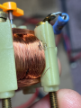
In your pic the lead-off wire is looking damaged at the bend. You can try bridge it with solder if the coil is open-circuit.
edit: there's no slack in that wire, so I would expect vibration and cold temps to stress it. Doing surgery to bridge and lengthen that wire a little is what I would plan, and a dab of silicone glue afterwards. It's a dirt bike...

gauge pic 1784727674111.png
 
Last edited:

Thread Starter

tmross

Joined Jul 22, 2026
17
Air-core gauges have TWO coils. Current through either coil can make the gauge needle move.
Hence there are three terminals. One coil is steady B-field (6V through 62 ohms say 100mA) and the second coil's current is through the sensor and varies.
Check for continuity on each of the two coils. Bad connections at the ends, soldering to the pins is one place for failure.
In your pic the lead-off wire is looking damaged at the bend. You can try bridge it with solder if the coil is open-circuit.
edit: there's no slack in that wire, so I would expect vibration and cold temps to stress it. Doing surgery to bridge and lengthen that wire a little is what I would plan, and a dab of silicone glue afterwards. It's a dirt bike...

View attachment 369818
I'll test coils for open-circuit, I think what you're seeing is just light shining on the bend though, I didn't see any issues there.
 

B-JoJo-S

Joined Jan 3, 2026
415
Post #18
You bypassed the resistor and the needle responded? Sounds like an open resistor. Either that or a bad solder joint.
Post 19
Sounds like an open resistor.
Replace the resistor.
Seems there's a consensus. But make sure the resistor is the problem first. Remove it and test it for resistance. If it's open, which I think it is - you will get an "OL" on your meter. If the resistor reads correctly then it's probably a bad solder joint. Solder joints DO fail from heat and vibration. In fact, it wouldn't hurt to reflow the solder joints and retest the meter.
 
Last edited:

MisterBill2

Joined Jan 23, 2018
27,847
It is also simple to check the resistor right in place. If it tests OPEN then certainly it needs to be replaced. If the value reads less than the marked value, then the resistor is connected across something else, and one end needs to be disconnectted to verify the resistor is OK.
BUT it is always useful to measure across the resistor in circuit before any other action, except for assuring that the circuit is not powered.
In this instance my guess is that the problem is not the resistor.
 

Thread Starter

tmross

Joined Jul 22, 2026
17
Seems there's a consensus. But make sure the resistor is the problem first. Remove it and test it for resistance. If it's open, which I think it is - you will get an "OL" on your meter. If the resistor reads correctly then it's probably a bad solder joint. Solder joints DO fail from heat and vibration. In fact, it wouldn't hurt to reflow the solder joints and retest the meter.
It is also simple to check the resistor right in place. If it tests OPEN then certainly it needs to be replaced. If the value reads less than the marked value, then the resistor is connected across something else, and one end needs to be disconnectted to verify the resistor is OK.
BUT it is always useful to measure across the resistor in circuit before any other action, except for assuring that the circuit is not powered.
In this instance my guess is that the problem is not the resistor.
Ok I tested resistor in circuit again last night and it showed 65 ohms. So should I rule the resistor out then? Or is there a scenario where a resistor tests good but is in fact not good. Does the voltage test I did suggest anything? There is a voltage drop of .02v across the resistor. That seems like, quite close to 0.
 

B-JoJo-S

Joined Jan 3, 2026
415
Are you testing across the resistor leads?
What is the resistor supposed to read? (what are the markings)
Are you testing across the connection points on the meter?
Have you tried reflowing the solder joints on the resistor?

The reason why I'm keyed in on the resistor is because you said when you shorted it the meter "Spiked". Not sure what you meant by that - did the meter swing fully across the gauge or did it just bump for an instant?

Testing with the resistor in circuit means you could be reading through the coil and not the resistor. That's why I suggested removing the resistor first, then testing the resistor OUT OF CIRCUIT..
 

B-JoJo-S

Joined Jan 3, 2026
415
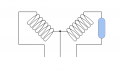
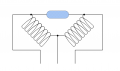
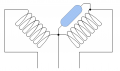
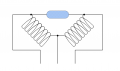
I don't know how the meter is made (electrically). I've made a drawing in the hopes to understand how it is made. I'm probably wrong. The resistor could be bridged between the two coils. Like I said - I don't know. And test for Ohms, not Volts.
Screenshot 2026-07-23 at 9.03.24 AM.png
Or:

Screenshot 2026-07-23 at 9.02.33 AM.png
Or:

Screenshot 2026-07-23 at 9.12.10 AM.png
 
Last edited:

Thread Starter

tmross

Joined Jul 22, 2026
17
Are you testing across the resistor leads?
What is the resistor supposed to read? (what are the markings)
Are you testing across the connection points on the meter?
Have you tried reflowing the solder joints on the resistor?

The reason why I'm keyed in on the resistor is because you said when you shorted it the meter "Spiked". Not sure what you meant by that - did the meter swing fully across the gauge or did it just bump for an instant?

Testing with the resistor in circuit means you could be reading through the coil and not the resistor. That's why I suggested removing the resistor first, then testing the resistor OUT OF CIRCUIT..
Yes I am testing across resistor leads
Resistor is rated 62 ohm 5%, 1 watt
I may have tried testing across connection points on meter too, I don't remember, will try when I get home from work.
Have not reflowed solder joints

Spiked is the wrong word now that you point it out, it jumps forward, bypassing the resistor causes sparks to fly and I don't want to hold it like that for long. It causes an immediate pronounced swing of the needle though. Here's the thing though, I do not understand this circuit at all, I don't know how or why this gauge works, its possible this resistor bypass test actually says nothing about the state of the resistor or anything else about this gauge, i.e. its possible a perfectly healthy gauge would behave in the same way if you bypassed the resistor. The "standard" test for this gauge, outlined in the manual, is connecting the sender lead to ground, which is supposed to send the needle into the red, but it doesn't.

I think its this one. I'll look closer at it later, and maybe attempt a hand drawn diagram of my own.
1784819552880.png
 
Last edited:

B-JoJo-S

Joined Jan 3, 2026
415
Keep in mind I don't know how that meter is made. All three of my drawings could be wrong. If you post more pictures of your meter it should be easier to determine what components are wired and where. Pictures of the back side as well as the front. More clearly show where each connection point on the back goes to where.
 

B-JoJo-S

Joined Jan 3, 2026
415
Fuel gauges from the 70's and earlier used a bi-metallic strip to move a needle. The fuel sender sent a current through a heating coil that warmed the bi-metallic strip and caused it to deflect. I don't recall ever taking apart a temperature meter though. Clearly the one you have is not a bi-metallic strip type of meter. (guessing here) the two coils oppose each other. The signal through the resistor (probably) changes the opposition to one of the two coils causing a magnet on an armature to swing thus displaying the relative temperature. But this is all guesswork based on what I think is some practical education. I was known as a child to take things apart to see how they worked. Didn't always understand them but I could kind of get an idea what was going on. My biggest fascination was with spark coils.
 

Thread Starter

tmross

Joined Jul 22, 2026
17
Heres a vid of someone taking apart an air core gauge

I see some similarities to mine, his resistor is on the bottom of the gauge. I think its similar principal though
 

MrChips

Joined Oct 2, 2009
34,981
If you were measuring resistance across the resistor, you were also measuring the resistance of the sender.
That is why you got a reading even if the resistor is open.

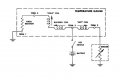
Temperature gauge.jpg
 

Thread Starter

tmross

Joined Jul 22, 2026
17
If you were measuring resistance across the resistor, you were also measuring the resistance of the sender.
That is why you got a reading even if the resistor is open.

View attachment 369837
The gauge has not been connected to the sender while doing all these tests. I have the gauge removed from the dash and on the bench.

The components on my gauge are arranged in different order than that diagram. For example the resistor connects the sender/unused terminal/and battery terminals and does not touch the ground terminal, whereas in the diagram the resistor connects the ground (1) and unused terminal (4).
 

Thread Starter

tmross

Joined Jul 22, 2026
17
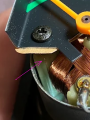
Well I probably just broke this thing for real. One of the coil wires broke off at the connection.
1784845667917.png

That broken wire was attached to the post at the top (where the resistor is soldered on). I pulled it a little to see if there was any slack and it just broke off further down. Thing is I can't really tell which coil it was coming off of, the inner or outer coil. Is there any way to salvage this or is it toast?
 

Thread Starter

tmross

Joined Jul 22, 2026
17
better question - can anyone recommend an electronics repair shop anywhere in the US that can fix this thing? These motorcycles were rare and it'll be very difficult to find a replacement.
 
Top