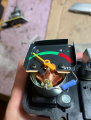
Temperature gauge stopped working

Thread Starter

tmross

Joined Jul 22, 2026
9
1784727674111.png
Hey everyone, this motorcycle (1988 Yamaha DT50LC) temp gauge stopped working entirely, I believe I have narrowed it down to the gauge itself and not any other component in the system. Troubleshooting steps in the manual say if the sender wire is touched to ground it should peg the needle to H, if not it is faulty and needs to be replaced. Well, there are no replacements available anywhere so I need to fix it. This gauge, which I believe is an air core gauge, has 3 terminals on the back: 6v +, ground, and one for the sender (which connects to the thermistor). To bench test it I hooked the + and - terminals to a 6v battery, then connected the sender terminal to ground, the needle did not move a hair. I've inspected the gauge and see no breaks in the coil wiring. The resistor measures at 69 ohms (it is rated for 62 ohm 5%). I did a test to bypass the resister by jumping the leads and the needle spiked, I don't know if that suggests anything though. I admittedly know nothing about electronics. Any ideas where the failure point is? Thanks
 

MrChips

Joined Oct 2, 2009
34,980
Your tests are indicating that the resistor is good and the meter movement is working.

This could mean a few things.
(1) There is a bad connection or solder joint.
(2) The problem is intermittent depending on physical stress on the resistor, wires and connections.
(3) From the photograph, it looks as if the solder connection between the resistor and the coil is touching the metal housing.
(4) The needle is sticking and not able to move freely.

Check these first:
(4) Can you move the needle easily with the touch of a feather?
(3) Bend the solder lug and resistor so that no part is touching the metal housing.

WARNING: Do not test the meter movement without a suitable value of resistance in series with the power source. Without the resistor, you are in danger of permanently damaging the coil and meter movement.
 

Thread Starter

tmross

Joined Jul 22, 2026
9
Your tests are indicating that the resistor is good and the meter movement is working.

This could mean a few things.
(1) There is a bad connection or solder joint.
(2) The problem is intermittent depending on physical stress on the resistor, wires and connections.
(3) From the photograph, it looks as if the solder connection between the resistor and the coil is touching the metal housing.
(4) The needle is sticking and not able to move freely.

WARNING: Do not test the meter movement without a suitable value of resistance in series with the power source. Without the resistor, you are in danger of permanently damaging the coil and meter movement.
Thanks, re: (3) its not touching, just photo perspective. (4) the needle moves freely, I can easily move it by hand and it returns to starting place. (1) I don't see anything jumping out at me re: bad connections/solder joints, it all looks good and intact.

And whoops I already violated your warning by bypassing the resistor leads for a test.
 

Thread Starter

tmross

Joined Jul 22, 2026
9
Did you measure the resistance of the sender through the operating range?
If by sender you mean the thermistor unit - no, since the gauge failed the "sender lead to ground" test, which should spike the needle, that indicates the issue lies in the gauge, according to the manual troubleshooting section.
 

Thread Starter

tmross

Joined Jul 22, 2026
9
If the thermometer pointer jumped on any manipulation-tinkering, the problem is anywhere else in wiring, soldering, resistor...
Ok, well since the needle spiked when I bypassed the resistor, I would assume that the + and - terminals on the gauge are conducting properly... I think. Perhaps something is going on with the sender terminal. Is measured 69 ohm out of spec for the 62 ohm 5% rating?

There just doesn't seem to be a whole lot to this thing... a resistor and some wire coil. what could go wrong.
 

Thread Starter

tmross

Joined Jul 22, 2026
9
Meter unit poles ?
Loss of magnetism ?
Is there a way to test for magnetism loss? I feel like that'd be the spookiest culprit. But I've read like a dozen threads about temp gauges not working and seems like every manufacturer says in the manual to just replace the gauge if its determined to be faulty, as if these things operate via black magic or something.

on the other hand, the fact that the needle did move when i bypassed the resistor, would indicate there must still be some magnetism in there, somewhere, right?
 
Last edited:

MrChips

Joined Oct 2, 2009
34,980
The next test is to vary the value of the resistance in series with the supply voltage.
Do you have access to a variable resistor, or what we call a "pot", short for potentiometer?
Something with a maximum resistance between 100 Ω to 1000 Ω should do.

Start with the pot set to its maximum resistance and gradually reduce the resistance.
You hope to see the needle start at C and gradually move towards H.
 

Thread Starter

tmross

Joined Jul 22, 2026
9
The next test is to vary the value of the resistance in series with the supply voltage.
Do you have access to a variable resistor, or what we call a "pot", short for potentiometer?
Something with a maximum resistance between 100 Ω to 1000 Ω should do.

Start with the pot set to its maximum resistance and gradually reduce the resistance.
You hope to see the needle start at C and gradually move towards H.
Do you mean substituting the pot for the resistor currently in place? What would that tell me exactly?

Or if you mean putting the pot between the battery + terminal and the + lead on the gauge, I'm also not sure I follow what that would accomplish, given that with 0 resistance the needle does not move.
 

Thread Starter

tmross

Joined Jul 22, 2026
9
Worth checking the wiring connection first, then the sensor itself with a multimeter if you have one — a loose connector or bad ground is usually the culprit with these. What type of gauge is it?
Its an air core gauge, I found this thread about them here, all way over my head https://forum.allaboutcircuits.com/threads/motorcycle-temperature-gauge-help.162221/

I think I can rule out bad wiring connections to the gauge, I am bench testing the gauge with a battery/test leads and the needle is not moving when it should be. If there is a bad connection somewhere, it is somewhere internal that I cant see it, which is weird cause theres just nothing really in there but wound coil and a magnet from what I understand.
 

MrChips

Joined Oct 2, 2009
34,980
Do you mean substituting the pot for the resistor currently in place? What would that tell me exactly?

Or if you mean putting the pot between the battery + terminal and the + lead on the gauge, I'm also not sure I follow what that would accomplish, given that with 0 resistance the needle does not move.
given that with 0 resistance the needle does not move.
I thought that you already tested the meter coil and it spiked.

I did a test to bypass the resister by jumping the leads and the needle spiked,
 

MrChips

Joined Oct 2, 2009
34,980
Do you mean substituting the pot for the resistor currently in place? What would that tell me exactly?

Or if you mean putting the pot between the battery + terminal and the + lead on the gauge, I'm also not sure I follow what that would accomplish, given that with 0 resistance the needle does not move.
Disregarding the inconsistent reports, If you substitute the pot for the resistor it would tell you the current and voltage required to give full-scale deflection of the needle. This would be a substantial step forward.
 

Thread Starter

tmross

Joined Jul 22, 2026
9
I thought that you already tested the meter coil and it spiked.
Disregarding the inconsistent reports, If you substitute the pot for the resistor it would tell you the current and voltage required to give full-scale deflection of the needle. This would be a substantial step forward.
Ok let me back up here, I don't think theres any inconsistent report.

With the +/- terminals on the gauge connected to +/- on battery I:
(1) Tested sender lead to ground - needle did not move (it should)
(2) Bypassed resistor on gauge, with sender lead still grounded - needle spiked.

When I said "given that with 0 resistance the needle does not move." I was referring to (1).
When I said "I did a test to bypass the resister by jumping the leads and the needle spiked" I was referring to (2), obviously.

There are 2 different reports (i.e. needle did not move; needle spiked) however they are not inconsistent, considering they were 2 separate tests on different components. I think maybe you thought I was reporting opposite results for the same test.

I hope that makes sense.

Moving on, I still don't understand what putting a pot in place of the resistor would tell me exactly. I already know the resistor is good, via multimeter. Is using a pot here like a backup test on the resistor? Can the resistor test good but actually be bad?
 
To bench test it I hooked the + and - terminals to a 6v battery, then connected the sender terminal to ground, the needle did not move a hair.
Accordingly it should have responded. You've localized the problem.
The resistor measures at 69 ohms (it is rated for 62 ohm 5%).
Did you remove the resistor from the coils to test it? You could be getting a false reading from the coil itself.
I did a test to bypass the resister by jumping the leads and the needle spiked.
You bypassed the resistor and the needle responded? Sounds like an open resistor. Either that or a bad solder joint.
 

MrChips

Joined Oct 2, 2009
34,980
Sounds like an open resistor.
Instead of measuring the resistance while it is in-circuit, measure the voltage across the resistor.
If you get full battery voltage, the resistor is open.

Disconnect the gauge from the sender and measure the resistance of the resistor.
 
If by sender you mean the thermistor unit - no, since the gauge failed the "sender lead to ground" test, which should spike the needle, that indicates the issue lies in the gauge, according to the manual troubleshooting section.
You are assuming that those instructionas are correct. I call those instructions a bit hard to believe.
The first step I would take is to check the sensor and the connection wire to that sensor. That would mean measuring the resistance from the sensor lead
THEN, verify that the supply voltage connection is actually connected, and likewise, the power return connection.
After those are verified to be OK, start checking the gage. Bypassing the resistor seems like a good way to assure that you need to get a replacement distlay. Checking the resistor "in place" should tell you if it is OK or open. Resistors like that one seldom fail shorted. Connection s of solid wire in the coils may fail because of the vibration.
 
Top