Facebook
 Google
 GitHub
 Linkedin
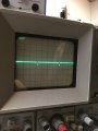
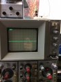
Dim display is likely caused by aging CRT. The only solution is to replace the CRT but is it worth it?Ok, I will look for one and buy it if I find it. So for the time being, what could be causing the dim display? I got it brighter by adjusting the unblanking center, but it is close to fully clockwise. The manual says it should be around the middle of the pot. I also took some voltage measurements and found the +48V points around Q863 and Q864 are at +20V. Adjusting the unblanking center gets it to +42V, but then you can't see the trace and the pot is fully counter-clockwise.
EDIT: It also looks like someone before me has replaced D405 (1N3714) and D455 (1N3713) which are both Tunnel Diodes also.
Tektronix 422 High Voltage Supply Problems
- Thread starter m2circuits
- Start date