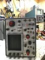
Just probed around the points indicated, getting no square wave to start off with at the input of the sweep generator. Perhaps a problem with the Sweep Trigger? On the input of T401 I'm just getting noise, would it be possisble to get a picture of what that point looks like on yours?
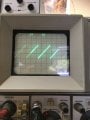
Hold the phone! Traces! And she sweeps! Was just poking around with my scope probe and started seeing a signal where I wasn't, and bam there is a trace now. But it won't trigger on the call signal, so I think my hunch of a trigger problem may be correct.
We now have to look at the SWEEP TRIGGER circuit <5>.
With the 422 CH1 INPUT on CALIBRATOR,
LEVEL set to AUTO,
probe the signal at the base of Q364. The test point is on R352 in the board picture below. You ought to see a 500mV p-p square wave at 1kHz centered about 0V.
We now have to look at the SWEEP TRIGGER circuit <5>.
With the 422 CH1 INPUT on CALIBRATOR,
LEVEL set to AUTO,
probe the signal at the base of Q364. The test point is on R352 in the board picture below. You ought to see a 500mV p-p square wave at 1kHz centered about 0V.
EDIT: I trace that 500mV square wave all the way to C377, once it passes through C377 it drops in amplitude to 20mV, the signal on the output of T401 is down in the noise.
Also, if you probe just before C377 you can adjust the TRIG LEVEL and watch the signal disappear and come back around 12 o'clock where the scope is supposed to trigger. So the trigger section is triggering but not relaying that info to the sweep.
I am going to guess that D375, tunnel diode 1N3719, is bad and needs replacing.
This is a very sensitive Ge diode and will be difficult to source at this stage.
Let me know if you find any.
I am going to guess that D375, tunnel diode 1N3719, is bad and needs replacing.
This is a very sensitive Ge diode and will be difficult to source at this stage.
Let me know if you find any.
Ok, I will look for one and buy it if I find it. So for the time being, what could be causing the dim display? I got it brighter by adjusting the unblanking center, but it is close to fully clockwise. The manual says it should be around the middle of the pot. I also took some voltage measurements and found the +48V points around Q863 and Q864 are at +20V. Adjusting the unblanking center gets it to +42V, but then you can't see the trace and the pot is fully counter-clockwise.
EDIT: It also looks like someone before me has replaced D405 (1N3714) and D455 (1N3713) which are both Tunnel Diodes also.
I tested the Tunnel Diode, and it seems to test fine, low ohms reading, and low voltage with a diode tester. Does that mean it's still good? And perhaps the problem is something else like a drifted resistor?
Ok, I'll borrow a friend's tomorrow. In the mean time I check R377 which says 39Ω but actually measures 390Ω on more that one of my meters. I don't have this value, but I'll get one tomorrow.
It's still measuring around 3Ω, and I did some quick research and a bad tunnel diode is said to have a high resistance reading when it fails. But all the same I just found a seller and ordered two of them.
 Facebook
 Google
 GitHub
 Linkedin