 Facebook
 Google
 GitHub
 Linkedin
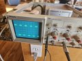
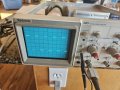
I have a vintage Tektronix Oscilloscope that I purchased in 1982. I was trying to use it on a project that I was working on, and found that although I was able to calibrate a 10X probe on channel 2, no adjustment of the probe (that worked on channel 2) really changed the appearance on the scope to look like a square wave.
I tried many local and non-local electronics repair operations, and found none that could fix it for me. In the mean time, I had purchased a "new" oscilloscope that was faster and relatively cheap.
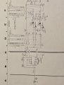
I would still like, for mainly sentimental reasons, to get my old Tektronix in working order. I have attached a portion of a schematic from the service manual.
If anyone is willing to help me, I can provide other schematic jpegs and videos of the oscilloscope screen (I couldn't attach the videos to this post).
I tried many local and non-local electronics repair operations, and found none that could fix it for me. In the mean time, I had purchased a "new" oscilloscope that was faster and relatively cheap.
I would still like, for mainly sentimental reasons, to get my old Tektronix in working order. I have attached a portion of a schematic from the service manual.
If anyone is willing to help me, I can provide other schematic jpegs and videos of the oscilloscope screen (I couldn't attach the videos to this post).
Attachments
-
 166.7 KB Views: 22


")


