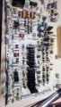
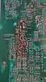
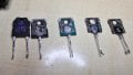
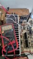
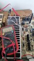
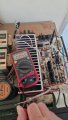
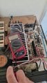
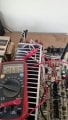
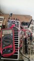
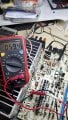
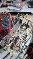
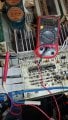
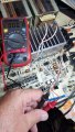
Technics SU VX-800 with blown components (another one)

Thread Starter

alprampo

Joined May 29, 2026
4
Hi all,

I landed here while searching for help on repairing this unit. It was my first "good" amplifier, bought when I was young, now I'm 55. About a year ago, it stopped working due to an accident.

It was left powered on on a covered terrace, with the right speaker cable left disconnected from the speaker and lying the floor. When it started raining, both the speaker cable and the 230V plug ended up underwater. As a result, the right channel smoked and destroyed all the power transistors.

While taking some measurements to diagnose the issue and comparing them with the left channel, I accidentally caused a short, blowing up the left channel as well.

It took a while to discover the thread started by Marius83 for a very similar issue, where MrChips and JoeJester provided great help.
in the last months i readd it completely, but issue is not 100% equal.
I have since replaced a large number of components. The amp is no longer in protection mode, but it's still not working properly. During my last attempt, the left channel started playing—not immediately after powering on, but after I moved a power supply transistor (the PCB is damaged from heating and the copper trace is gone). However, shortly after, resistor R513 burned out.

At the time, I had all components installed but was testing with only one pair of power transistors per channel instead of four. Could the missing transistors have caused R513 to burn out?

Thanks in advance for the help!

Alberto
 

Pyrex

Joined Feb 16, 2022
532
Hi all,

I landed here while searching for help on repairing this unit. It was my first "good" amplifier, bought when I was young, now I'm 55. About a year ago, it stopped working due to an accident.

It was left powered on on a covered terrace, with the right speaker cable left disconnected from the speaker and lying the floor. When it started raining, both the speaker cable and the 230V plug ended up underwater. As a result, the right channel smoked and destroyed all the power transistors.

While taking some measurements to diagnose the issue and comparing them with the left channel, I accidentally caused a short, blowing up the left channel as well.

It took a while to discover the thread started by Marius83 for a very similar issue, where MrChips and JoeJester provided great help.
in the last months i readd it completely, but issue is not 100% equal.
I have since replaced a large number of components. The amp is no longer in protection mode, but it's still not working properly. During my last attempt, the left channel started playing—not immediately after powering on, but after I moved a power supply transistor (the PCB is damaged from heating and the copper trace is gone). However, shortly after, resistor R513 burned out.

At the time, I had all components installed but was testing with only one pair of power transistors per channel instead of four. Could the missing transistors have caused R513 to burn out?

Thanks in advance for the help!

Alberto
Circuit diagram needed
 

Thread Starter

alprampo

Joined May 29, 2026
4
Thank you so much Pyrex for the reply!

Here is the service manual. I had to remove several pages due to the attachment size limit, but I can provide more if needed.

Below is a partial list of the components replaced during the first review (currently, I don't have access to the bench where the amplifier, notes, and spare parts are):

  • Output Transistors: All 2SA1265 and 2SC3182 (Most likely with fakes for the A1265, but no smoke yet)
  • Transistors:
    • Q420, Q422: 2SC3311A
    • Q430: 2SA1535A
    • Q418: 2SD1761
    • Q428: 2SC3944A
    • Q426: 2SA1123
    • Q424: 2SC2631
  • Diodes: D414, D416 (MA165)
  • Capacitors: C425, C426 (1 µF / 100 V - both exploded)
  • Resistors:
    • R446: 100 Ω
    • R509, R510, R512, R513: 680 Ω
    • R506 6.8 Ω
As soon as I can, I will also post photos of the damaged PCB.
Alberto
 

Attachments

Pyrex

Joined Feb 16, 2022
532
I don't thing the missing pair of output xistors cause damage to the R513.
It's pretty strange that two capacitors C425/426 had exploded. They could only explode due to much higher voltage or because of incorrect polarity.
Since the device was affected by water, check all the transformers, you’d need a megohmmeter for that. Disconnect the secondary circuits from the transformers and measure the AC voltages; they should match those shown in the circuit diagram.
Some low-resistance resistors, not wire-wound, may show a good reading when measured, but when used with higher current, they can significantly increase their resistance.

And also keep in mind that these amplifiers are not easy to repair, because if you replace one bad component, and there are other damaged components left, when you power up the device, there will be smoke again.

For the start of the repair, limit yourself to fixing just one channel; once it works, you can compare the voltages and resistances with the readings of the other channel.
During repairs, connect the speakers through a resistor, about 50 ohms, because if there's DC voltage at the output, you could damage the speakers
 

Thread Starter

alprampo

Joined May 29, 2026
4
Dear Pyrex,

Thanks for your suggestions.

Just to clarify, the amplifier itself did not get wet. Only the AC plug and the right channel speaker wires fell into the water while the unit was powered on and the speaker switch was set to A+B. The connected speaker is still working, as the main 220V circuit breaker tripped immediately.

I was confident that all damaged parts had been replaced. I checked every single transistor and resistor individually (it took an eternity) and replaced all the burnt components. I forgot to mention earlier that IC402 was actually cracked into two pieces, which I only discovered once I desoldered it.

I then tested the unit using a 50W halogen bulb in series with the AC line (halogen bulbs seem to be out of production now, so that's the only rating I had at home). The bulb behavior seemed fine, but there was no sound. However, after touching/reflowing Q651 and Q653, sound started playing on the left channel, but R513 immediately went up in smoke.

Since the issue doesn't appear to be related to the missing power transistors, I am going to re-check the PCB and replace the damaged resistor.

I've already read through the entire thread here:

https://forum.allaboutcircuits.com/threads/technics-su-vx800-amplifier.143789/

For reference, here is the link to the full high-resolution service manual:

https://drive.google.com/file/d/1tsiRmSXY-8_kohS8HKWzvBpnM8mMgfd7/view?usp=sharing

Any advice or suggestions on how to proceed would be greatly appreciated—such as whether I should remove key components to work on one channel at a time or perform specific isolation tests. I would really love to fix this myself!

Thanks,

Alberto
 

MrChips

Joined Oct 2, 2009
35,055
Just to let you know that I am following your thread. To be fair to other users, I am working on their amp repairs first and I will come back to your problem when I get the chance. In the meantime, I can give you some tips on how to proceed.

1) For now, refrain from removing components. Take clear, high resolution photos of both sides of the boards.
2) Disconnect all loudspeakers to avoid damaging them.
3) Build the AC lamp load circuit posted to avoid blowing two many components. Use plug and outlet that matches your 230 VAC EU style outlets.

1788011380456.png
 

Thread Starter

alprampo

Joined May 29, 2026
4
Hi MrChips,

Thank you so much, I really appreciate your time and help!

Just for context, my Dim Bulb Tester setup is currently in the exact same state as yours, except for the power switch—I'm just using the switch on the power strip instead.

As anyone who knows these devices a bit is aware, Technics completely forgot to implement a heatsink for the medium-power transistors. On top of that, the mainboard on my unit is in very bad condition with several charred areas, making it probably one of the most beat-up amplifiers you could ever come across—though until the accident occurred, it was in full working order!

I'll follow your tips, take clear high-res photos of both sides of the boards, keep the speakers disconnected, and use the lamp limiter circuit before doing anything else.

Looking forward to your guidance whenever you have time.

Thanks again,

Alberto


Here a preview, better photos will come.

20250919_194401.jpg
 

MrChips

Joined Oct 2, 2009
35,055
Sorry, I did not realize that this is the same beast that we wrestled with for three years starting in Dec 2017 with Marius83.
Hold off on the photos for now. Give us the symptoms.

1) Disconnect all loudspeakers.
2) Measure the voltages at the output (+) with respect to ground.
3) Measure the voltages at TP501 (+) and (-) and TP502 (+) and (-) with respect to ground.
4) Measure the supply voltages +60 V and -60 V with respect to ground if you know where to find them.
 
Top