Sync/reset pulse on a CD40106 astable

Thread Starter

devinw

Joined Dec 2, 2018
32
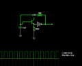
So I've been messing around alot with the 40106 inverting hex schmitt trigger IC and have been trying to figure out a good way to get a sync pulse coupled into it from another oscillator. I had a simple "aha" moment and put a diode between the cap and the schmitt input, and then another diode at that node with a ~9V narrow pulse from the other oscillator. I plugged into LTSpice and it works!...but then I went to build it and nooooope! The basic astable vibrator of course works great, but as soon as I add that diode between the cap and the input it goes CRAZY and oscillates at like 2MHz...

I figured maybe for some reason the 40106 needs some kind of damping between the diode and the input and tried a 470 uH inductor but that didn't help. I also tried some series caps on either side of the diode, which helped, but the whole thing seems unstable and if you just touch the diode it makes strange frequency shifts and couples in some dirty 60 cycle hum or something.

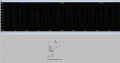
So, my analog guru friends here, do you have any ideas on how to execute this? Atached is a shot of the LTSpice model which is more or less showing what I would like to see in reality. The blue and green waves are the normal square and triangle that you get off the output and input nodes of the astable, and the red is the sync pulse, which you can see creates some sync waveforms.
 

Attachments

Thread Starter

devinw

Joined Dec 2, 2018
32
Yeah I thought about that too and tried it. The only is at lower frequencies the sync completely kills the 50% square output (the output of the inverter) because the charge discharge resistor (1M shown the in the simulation) is quite large.
 

crutschow

Joined Mar 14, 2008
34,285
If you really need a 50% square-wave output than operate the astable at double the frequency you want, and run its output through a divide-by-two toggle flip-flop.
 

Thread Starter

devinw

Joined Dec 2, 2018
32
Oh, it already does output a 50% with that cap value at the frequenices I need. It's quite clean actually. I mean, +/- 2-3 percent on the duty cycle.

Anyway, I found another solution that may just work for the syncing and scrapping the diode, using a NPN buffer of sorts before the schmitt input. It works in simulation, but I'll test it in reality tonight.
 

Thread Starter

devinw

Joined Dec 2, 2018
32
I just put the + of the timing cap to the base of an NPN, +15V to the collector, and the the emitter goes to the input of the inverting schmitt, with a 500k resistor to ground at that same node.
 

AnalogKid

Joined Aug 1, 2013
10,987
The NPN buffer had nothing to do with making your circuit work. The 500K resistor is what fixed things.

A CMOS input is pair of MOS transistors, and the gate input of a MOSFET is a capacitor, a very thin sheet of glass between the gate terminal and the channel. In the post #1 schematic, the input capacitance is charged up through the diode, and then left floating when the diode is reverse-biased. That charged capacitor holds the input high during what is supposed to be the next half-cycle, driving and holding the output low. In post #10, the 500K resistor (note - add reference designators) discharges the input capacitance so the circuit functions normally. If you keep the resistor and go back to the diode, the circuit still will function.

Another note - this is why we always ask for the schematic. In an EE forum, n.o.t.h.i.n.g. conveys more information about both the circuit and the designer.

ak
 

Thread Starter

devinw

Joined Dec 2, 2018
32
AnalogKid, I know the circuit works fine with the buffer. It's just the basic astable vibrator from the 40106 datasheet :). One cap, one resistor, one schmitt inverter.

The thing I was looking at, as I described in the first post is a way to introduce sync pulses into the circuit, which required some isolation from the feedback loop of the oscillator. I had tried a diode, which worked in simulation, but not in reality. Then I added the NPN buffer and it worked. The idea is I can introduce a pulse at the node between the output of the NPN buffer and the input of the schmitt inverter. It works.

Thanks and I'll remember to post schematics straight off from now on!
 

AnalogKid

Joined Aug 1, 2013
10,987
The thing I was looking at, as I described in the first post is a way to introduce sync pulses into the circuit, which required some isolation from the feedback loop of the oscillator. I had tried a diode, which worked in simulation, but not in reality. Then I added the NPN buffer and it worked.
I got that. My point was that if you keep the resistor from the 40106 input to GND, you can delete the transistor, go back to your original diode idea, and it still should work.

ak
 

Thread Starter

devinw

Joined Dec 2, 2018
32
I tried that. Works on the sim, but also makes the 40106 freak out and osciallate at like 2MHz. ! Very odd. Tried it on multiple chips too. !
 
Top