Rewiring a machines and controllers to operate in sync

Thread Starter

NYMM2346

Joined May 24, 2021
7
I purchased a 2 sets of hoists that each have a wired and unwired remote. I would like to operate both machines with 1 wired remote and 1 unwired remote by wiring two motors in parallel using a 4 pin wire splitter. The motors operate on a maximum of 10 Amps, I believe the contractors, motor, and capacitor can handle 20 AMPS (based on my explanations and math below).

Questions:
1. whether my plan to wire the device should work in theory so that the controls will work on both devices simultaneously.
2. I can test the feasibility of using a splitter without causing damage to the devices?
3. Would the current 1.5 mm diameter wires of the device be sufficient or would they need to be replaced to ensure long term viability with larger wires or wires with better insulation?
4. Do I need to do anything else to ensure this works or are my calcuations, inferences and proposed circuitry accurate?


1719428846612.png
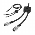
The output from the IEC to the hoist is carried in 4 wires. When 2 are powered then the motor spins in one direction, when the other 2 are powered it would go in the other direction. The connection is made through a 4 pin M12 circular connection. Therefore, I believe the best case scenario would be to use a Y splitter which can then be plugged in to both devices. I believe the wiring uses 1.5 mm wires, which should be 15 AWG, but this is based on the casing of the output wire which has printed on it 4 x 1.5 mm^2 and measuring the caliber of the external diameter of the wire which is 2.5 mm.

1719428864748.pngY-splitter
1719430665204.png

Main components

Hoist Motor110V-60Hz and has an input power of 1200W (~10 Amps)*
* power/amps would likely vary depending on weight lifted
CBB60 Capacitor160 µF ±5% SH, 250VAC 50/60Hz, 25/70/21 C PO
CJX2-12 AC contactor x 2Ui: 660V, Ith: 25A
Ue , 220, 380, V
AC-3
Ie, 12, 12, A
pe, 3, 5.5, KW
Internal wiring with ("DIAN XIAN" PVC insulation)1.5 mm² (approximately 15 AWG)

Can the components handle the amps?
The CJX2's say they can handle 25 amps, the CBB60s dont say and the 15 AWG wire may vary based on the insulation (so this I'm not sure about)

Capacitor: 25 - 30 A

Capacitor @ 50 Hz:
I = 2π × 50 × 160 × 10^-6 × 250
I ≈ 12.57 × 0.008 × 250
I ≈ 25.14 A
Capacitor @60 Hz:
I = 2π × 60 × 160 × 10^-6 × 250
I ≈ 12.57 × 0.0096 × 250
I ≈ 30.17 A

Wires 12.5 - 22.5 Amps
This depends on the property of the wires and insulation used and I am using a table assuming that these standards are applicable to this electronic device based on table 310 below. I believe the wires are copper (I am trying to learn more about the properties by contacting the manufacture). I also think it might be important to note that the Amps being drawn are probably dependent on the heaviness of the load lifted and how frequently the device is being used. Since it will mostely remain idle, and the load will only vbe around 1/4 of the max load in general I imagine the total amps will usually be less and the wires shoudl not overheat (but I think experience will help to answer this question)

1719432762377.png

Breaker

I would switch to a single pole 30 Amp breaker to ensure it doesnt fail at 20.

I will leave some images of the inside of the device for reference:

Capacitor

1719434354152.png

Power box
1719434448221.jpeg


Y splitter
1719434468984.jpeg

CJX12

1719434494090.jpeg

Again my questions are

1. whether my plan to wire the device should work in theory so that the controls will work on both devices simultaneously.
2. I can test the feasibility of using a splitter without causing damage to the devices?
3. Would the current 1.5 mm diameter wires of the device be sufficient or would they need to be replaced to ensure long term viability with larger wires or wires with better insulation?
4. Do I need to do anything else to ensure this works or are my calcuations, inferences and proposed circuitry accurate?
 

Attachments

ApacheKid

Joined Jan 12, 2015
1,762
I have a suspicion that there'll be problems unless each motor has its own start capacitor, using a single capacitor to start two induction motors in parallel strikes me as leading to unreliable starting. How many wires come out of the large capacitor, two or three? I suspect its two because the image of the capacitor shows just a single capacitance value.

My approach would be to use both units, that is both sets of contactors and so on, as is and use just a single control wire to activate each of them and use a single remote control receiver to also activate the two contactors. This will eliminate concerns about cable size and start capacitor behavior and so on.
 
Last edited:

ApacheKid

Joined Jan 12, 2015
1,762
Also bear in mind that there's no likelihood of the two motors starting at the exact same instant or running at the exact same speed, they'll be close for sure but if you need them to run in step to any high degree, that's something that I'd be concerned about.

By the way where are the hoists described? where did you buy them? do they have a make/model number or anything?
 

MaxHeadRoom

Joined Jul 18, 2013
30,557
Second that!
The best way is two separate contactors wired to operate simultaneously, each with sperate O/L's that are interlocked to prevent only one coming on line if one of the O/L were to trip.
 

ApacheKid

Joined Jan 12, 2015
1,762
So basically retain two of these

1719436539950.png

But in one of them remove the receiver module. Then wire the output from the other receiver to drive the one that had ist receiver removed. Similarly for the wired mode, just have the wire from that manual controller, fed into both units and remove the other manual controller.

I suspect the signal strength from the receiver module will be sufficient to drive both controllers, that's a guess so might need verifying but its likely a safe assumption.
 

LowQCab

Joined Nov 6, 2012
5,101
If either Winch has even slightly more, or less, weight applied to it,
then the Winches will quickly get out of sync with each other after only a few cycles.

How do You propose to correct this when, ( not if ), this happens ?

Personnel-Safety around an Overhead-Load should be the first consideration.

The overall mechanical-design, and what is being lifted, must be the second things to be considered.

Using a single Winch is a much better plan to start with.

Any Automation of a winch is going to be a serious liability in some way.
.
.
.
 

Thread Starter

NYMM2346

Joined May 24, 2021
7
If either Winch has even slightly more, or less, weight applied to it,
then the Winches will quickly get out of sync with each other after only a few cycles.

How do You propose to correct this when, ( not if ), this happens ?
This is a good issue that I had not considered, as this is not advertised on the winch specs. As I understand, you are saying that weight applied to the winches will cause one winch to move faster or slower than the other, which might be related to force/velocity?

I believe the following would apply:

In my use case, it might not be an issue since I am relying on the second winch as a backup of the first unit. The total load will not exceed the load of 1 hoist. Therefore, if they are out of sync and Hoist A is shorter, it will carry all of the load, move slower, and hoist B will move faster until it equilibrates. Either A or B will end up shorter and then the process should repeat. Does this seem accurate?
 

Thread Starter

NYMM2346

Joined May 24, 2021
7
So basically retain two of [Hoists]

But in one of them remove the receiver module. Then wire the output from the other receiver to drive the one that had ist receiver removed. Similarly for the wired mode, just have the wire from that manual controller, fed into both units and remove the other manual controller.

I suspect the signal strength from the receiver module will be sufficient to drive both controllers, that's a guess so might need verifying but its likely a safe assumption.
This seems logical. If I understand what you are saying correctly. Instead of rewiring the output, I would rewire the input, the controller wire so that it attaches to both units? For example, if the wired remote has a 3 wire input of Red, Yellow and White going into positions 1B, 22A, 22B of Hoist A, I would split this wire so that it also connects to the same positions in Hoist B?
 

LowQCab

Joined Nov 6, 2012
5,101
A Winch "backing-up" another Winch ?????
I would definitely like to see the proposed mechanical-layout that would make this work reliably.

Forget about the Electrical-Control issues until the mechanical-problems are worked-out.

What is the reasoning behind using 2 Winches ?
If one Winch fails, it will turn the loose Steel-Cable into a rat's-nest of a tangled-up-disaster.
.
.
.
 

ApacheKid

Joined Jan 12, 2015
1,762
This seems logical. If I understand what you are saying correctly. Instead of rewiring the output, I would rewire the input, the controller wire so that it attaches to both units? For example, if the wired remote has a 3 wire input of Red, Yellow and White going into positions 1B, 22A, 22B of Hoist A, I would split this wire so that it also connects to the same positions in Hoist B?
Also, the remote control - radio? infrared? - could be used to control both units if each unit is set to the same "channel".
 

Thread Starter

NYMM2346

Joined May 24, 2021
7
Also, the remote control - radio? infrared? - could be used to control both units if each unit is set to the same "channel".
The wireless remote is RF, but currently only will allow 1 pairing with 1 device. I am replacing the receiver and remotes so that multiple devices can be paired simultaneously.
A Winch "backing-up" another Winch ?????
I would definitely like to see the proposed mechanical-layout that would make this work reliably.

Forget about the Electrical-Control issues until the mechanical-problems are worked-out.

What is the reasoning behind using 2 Winches ?
If one Winch fails, it will turn the loose Steel-Cable into a rat's-nest of a tangled-up-disaster.
.
.
.
I'm not sure if I understand why you are skeptical from a mechanical point of view? But the goal is for a second hoist to act as a safety should the first fail.

In this setup. You have Hoist A secured at point A, Hoist B secured at point B. The load is stabilized using rails. Each hoist can lift the entire load. If hoist A or any of its connections fail then you have hoist B acting as a backup (and vice versa).

1719507153325.png


An alternative, but costlier approach, that I have seen is securing a self-retracting line to protect against failure. These devices are also costlier.
 

LowQCab

Joined Nov 6, 2012
5,101
Your Block-Diagram,
while it far exceeds the quality of some of the Pencil-Scribbles we've seen here,
doesn't even begin to scratch the surface on the amount of additional information required.

As shown,
your idea will be trouble-prone, to say the least, and possibly even dangerous.
.
.
.
 

panic mode

Joined Oct 10, 2011
4,864
the Y-splitter that you have shown is meant for low power sensors and actuators, max rating is 30VDC and 3-4A, depending on brand. Usually they have wires 0.25-0.34mm^2 which is way too small for what you are planning to use it for.

even if you go from M12 to 7/8" you need to check the ratings carefully, as they are likely to be only good for 8A
1719519575329.png
 
Last edited:

MisterBill2

Joined Jan 23, 2018
27,164
If the goal ( which should have been described in post #1) was "reliability thru redundancy,", there are ways ti achieve that, and this is not one of them. There are load sharing schemes and redundant operation schemes, and live backup schemes. Not like what has been presented and discussed.
 

Diggerman

Joined Oct 1, 2018
2
This alarms me considerably having worked on cranes and hoists. Cranes and hoists are designed to fail safe, this is allegedly a 'backup' so if hoist A fails hoist B takes over however no consideration has been given to the fact that hoists have electromagnetic brakes or conical rotors on the hoist motor to ensure in the absence of power everything is locked in place. So if the hoist fails the brakes come on. The back up will now drag it through the brakes, this can lead to catastrophic failure of brakes, hoist motors etc at the very least wind up with a lot of chain or rope all over the floor. Running two hoists in tandem involves a lot of work both in synchronisation and safety control, what is being proposed here is basically a safety nightmare. Far easier in the event of hoist failure is to have a spare and swap them over if they are small, done with a scissor lift it can be pretty quick as along as you can get the load off.
 

strantor

Joined Oct 3, 2010
6,875
the Y-splitter that you have shown is meant for low power sensors and actuators, max rating is 30VDC and 3-4A, depending on brand. Usually they have wires 0.25-0.34mm^2 which is way too small for what you are planning to use it for.

even if you go from M12 to 7/8" you need to check the ratings carefully, as they are likely to be only good for 8A
The M12 connector was the first problem I saw, and was surprised to scroll through so many replies without it being addressed. Then when it was addressed, I was surprised to see it stated as having a max voltage of 30V. I use many 120V sensors with M12 connectors so that struck me as being in error. I looked it up and found that it depends on the pin count. Actually the 4-pin cable should be fine with regards to voltage, but current is definitely a problem.

Screenshot_20240702-061651_Chrome.jpg

I am glad this came up because I might have assumed 5+ pin M12 connectors are rated for higher voltage because the more common 4-pin models are.
 

MisterBill2

Joined Jan 23, 2018
27,164
I also noticed the "Y" splitter but that was the less urgent flaw, and it would fail the first time a motor load was applied. And certainly would not be accepted for motor power in any industrial context that I am familiar with
 

panic mode

Joined Oct 10, 2011
4,864
the first post mentioned M12... then the later posts showed images of M8. Voltage rating depends on insulation and spacing between contacts and on M12 variants with 5 or more contacts, the distance is smaller and smaller... same goes for M8...

not sure where the table in #16 came from but it is typical.
note that it shows A-coded type which is used for DC only. AC version uses C-coding. Even there more contacts means they are closer to each other so voltage and current ratings are lower:
1719931907241.png

There is also L-coded type (just to name one) which allows more current but it is nowhere nearly common/popular as A-coded variant
https://www.connectors.co.nz/connectors/circular-connectors/m12-coding-explained/
 
Last edited:

MisterBill2

Joined Jan 23, 2018
27,164
Aside from all the other concerns, starting and stopping two motors together does not make them synchronized. Sometimes fairly close, but not exactly.
 
Top