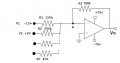
Hello, I'm new here and with minimal knowledge to electronics, I'm working part time for an electronics company to help fund my studies. I am faced with the following inverting op-amp circuit to modify R2 to work with a potentiometer instead. V1=-15 and V2=+5 and actually 7 resistors (390K - 47k) at the node "A" where only 1 at a time is selected according to a panel selection so that Vout drops from +1v ~ 0.2v. (i'm pretty sure that's what I measured). Originally controlled from a microprocessor thru a 4051 that selects the resistors according to the panel selection. I hope this all makes sense to someone. First, I don't understand how to write out the KCL the negative supply and current flow are confusing me. Btw, does anyone know of a free simulation app to help me with this kind of thing? thank you all in advance, have a great day
Attachments
-
 40.9 KB Views: 49

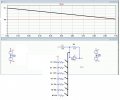


 - How the SAR code works.gif")
 ) crashed so the following has sign errors ...)