Summing Amplifier + Bandpass Filter

Thread Starter

Yeye

Joined Nov 12, 2019
47
Hey guys,
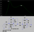
I bought one of those mono amplifier boards for subwoofers etc. Since it only has 1 input channel ( and ground ) and no Bandpass filter ( which i need, because i wanna use it as a subwoofer amplifier ) I tried developing a Circuit which combines those 2 circuits. I did that by using
http://falstad.com/mathphysics.html
the analog Filter and the analog Circuit simulator applet. Both circuits worked ( IN THEORY ) just as i wanted them to. Screenshot (28).pngScreenshot (33).png
( The 2 signal sources are the Left and Right channel from my Aux cable/3.5mm Phone Jack )
Im quite sure the summing amplifier should work just fine as i planned it ( correct me if not ).
But finally after recieving the PCB and the Components and testing it all, it didnt work. After trying to only use the Mono sum part, i heared noise and very light music ( my input signal ) when connecting a test speaker ( I dont have measurement equipment accurate enough for this )...
Is the reason just bad contacts or why doesnt it work?
Thank you in advance
 

Zeeus

Joined Apr 17, 2019
616
Hi : neophyte here but just trying : you'll get help you need soon

What power supply is used for the left image circuit? and not really a problem but next time add a resistor to non inverting input (parallel comb. of resistors at inverting)
 

Thread Starter

Yeye

Joined Nov 12, 2019
47
Hey, i used a small board to get -12v GND and +12v out of a +12v power supply. So i used +12v as +VCC GND as Ground and -12v as -VCC. I used that configuration for both circuits.
 

Audioguru again

Joined Oct 21, 2019
6,673
You are making a filter for a subwoofer but the filters are cutting most bass sounds and passing only a couple of tones.
You want a lowpass filter for the subwoofer amplifier, not two bandpass filters. You also need two highpass filters for the ordinary stereo sounds. Your filters are called "Multiple Feedback Bandpass Filters".

Where will you find opamps that can drive high currents into your extremely low resistor values?

I simulated your filters:
 

Attachments

crutschow

Joined Mar 14, 2008
34,283
i used a small board to get -12v GND and +12v out of a +12v power supply. So i used +12v as +VCC GND as Ground and -12v as -VCC.
You need two power supplies to get plus and minus voltages for AC signal amplification, otherwise you will clip 1/2 of the signal.

Alternately you can generate a virtual ground at 1/2 the single supply voltage, while AC coupling the input and output signals to block the DC offset in the signal (example below).

1573586435760.png
 

Thread Starter

Yeye

Joined Nov 12, 2019
47
Thank you guys for your answers!
1.:
Its Output is around 100mA... Is that too low?
2.:
Isn't this just a 2nd order bandpass? Thats just what it should be... are those resistor values really too low? I mean were dealing weit around 2v rms as far as i know ( as i said phone Jack voltage)
3.:
As far as i know, you can get -12v referenced to ground by using a 50% duty cycle +12v square Wave and a diode capacitor configuration... The board i've got really Outputs 12v and -12v referenced to real ground... Thats the way opamps should be powered isn't it?

*attached to 1:
https://rover.ebay.com/rover/0/0/0?mpre=https://www.ebay.co.uk/ulk/itm/332703430955Thank you in advance again
 

Audioguru again

Joined Oct 21, 2019
6,673
I simulated both of your bandpass filter together to show the awful frequency response.
Then I simulated a second order Sallen-key Butterworth lowpass filter for the subwoofer amplifier. Both stereo channels need matching highpass filters.

I recommend third-order filters since even order filters cancel at the crossover frequency.
 

Attachments

Audioguru again

Joined Oct 21, 2019
6,673
Thank you guys for your answers!
1.:
Its Output is around 100mA... Is that too low?
A cheap LM833 dual opamp has low distortion with a 2k ohms load. Your 700 ohms resistor will kill it. An expensive OPA2134 dual opamp has low distortion with a 600 ohms load. Your resistor values are too low.

2.:
Isn't this just a 2nd order bandpass?
You want a lowpass filter for a subwoofer, not a bandpass filter. Let the signal source cut very low frequencies.
A bandpass filter is made with a lowpass filter plus a highpass filter. Why do you have two narrow frequency bandpass filters?

3.:
As far as i know, you can get -12v referenced to ground by using a 50% duty cycle +12v square Wave and a diode capacitor configuration... The board i've got really Outputs 12v and -12v referenced to real ground... Thats the way opamps should be powered isn't it?
Why use a Mickey Mouse negative supply circuit that has a buzzing sound on it? Any opamp works perfectly when it has a single positive supply, its input is biased at half the supply voltage and has input and output coupling capacitors to block the DC. You were shown how. The Chinese power supply converter circuit has no detailed spec's like how much noise and the noise frequency it makes.

I simulated your two bandpass filters connected together to show you the resulting awful frequency response.
I also show a second-order Sallen-Key Butterworth lowpass filter. The stereo amplifiers each need a matching highpass filter.
I recommend using 5hird-order filters since even-order filters cause cancellation at the crossover frequency.
 

Attachments

Last edited:

Thread Starter

Yeye

Joined Nov 12, 2019
47
Do i not need a subsonic filter? Thats why i wanted that bandpass stuff... ( To be honest, i dont know how the filter i Made works... rts just what i got recommended from paul falstad Website)
Isnt third order a bit too much?
I have a TL072 as op amp by the way...
Thank you for your explanations
 

crutschow

Joined Mar 14, 2008
34,283
The usual preferred speaker crossover is the Linkwitz-Riley Filter since the sum of the two responses gives a flat response as you go through the crossover frequency.
Other filters will give a dip or peak of the sum as it goes through the crossover.
For example, two equal-frequency Butterworth LP and HP filters will have a +3dB peak in their sum at the crossover point.

The filter consists of a low-pass filter with a Q of 0.5 for the subwoofer and a high-pass filter for the other speakers, also with a Q of 0.5.

The LTspice simulation of such a filter, using 2-pole Sallen-Key filters with a 80Hz crossover (common sub crossover frequency) is below:
(Notice that both filters use the same component values).

Because of the filter phase-shifts, one of the signals needs to be inverted for proper summed response.
This is done below with inverter U3, but could be done by just inverting the connection to one of the speakers in the system.

Notice that the summed response (red trace) is perfectly flat.

The website I used to calculate the component values are LP and HP.

I don't think you need a subsonic filter unless your subwoofer has a substantial response below 20Hz, and you are listening to vinyl with a turntable that has rumble.
I have seen a subwoofer responding to turntable rumble with the cone slowing going in and out at the turntable revolution rate.

1573606896707.png
 

Audioguru again

Joined Oct 21, 2019
6,673
Do i not need a subsonic filter? Thats why i wanted that bandpass stuff... ( To be honest, i dont know how the filter i Made works... rts just what i got recommended from paul falstad Website)
Isnt third order a bit too much?
I have a TL072 as op amp by the way...
Thank you for your explanations
Where would subsonic frequencies come from? Not from a microphone and not from a recorder.
Oh, maybe if you are recording a band who are playing during an earthquake. Your bandpass filters pass only a few musical notes which is not what you want. The horrible frequency responses I showed say that your circuit was designed by somebody who knows nothing about an audio filter.
A third order filter has slopes a little steeper than second order but its phase shifts do not cancel outputs like even-order filters do.

The TL072 dual opamp was one of the first hifi opamps that I have used for many years. It works fine when you keep its input level low enough that it never goes within 4 volts from its negative supply voltage.
 

Audioguru again

Joined Oct 21, 2019
6,673
I have not thought about vinyl records and their wow and flutter for 30 years.
I doubt that the audio system in an old disco uses a subsonic filter. They naturally cut frequencies below about 30Hz.
 

Thread Starter

Yeye

Joined Nov 12, 2019
47
Okay firstly thank you for responding again... You kind of "need" a subsonic Filter when dealing with bass reflex subwoofer enclosures... They create a cutoff Frequency Fc , The frequency band below that certain Fc is nearly unhearable and makes the speaker cone move way too far which could result in damage or complete distruction. Thats why i wanna use such a subsonic, The subwoofer enclosure i developed gots its cutoff Frequency at 36hz which is quite high ( It is a small woofer, -> short bass reflex port -> it would need a small port area wich would result in hearable air noise -> still use large enough port area -> Cutoff frequency goes up )
Okay so if i use the lower part of crutschow 's Filter, I have the Filtering part... Until now, i only got the Power supplys for my amplifier board ( 2 times 50v -> +/- 50v input ) which i also wanted to use for the pre amping / Filtering station... Since i couldnt find a 50v opamp, i got myself 2 buck converter from 50v to 12v. I could maybe use them in series to get +-12v, right? So i have to bias ( As you said ) the input signal with 12v dc... How to do that? Then, only the input and output capacitors arae missing... Which values should i use for them? ( These caps are Ci and Co in the picture of crutschow s first answer right?) And then it should be done if i understood correctly... Are there no problems if i feed the amplifier board with a biased signal and a virtual ground (i suppose) and then the amplifier Board does the same (because we only got virtual +-50v and not real +-50v)?
So at the output of everything i get a +62v biased signal at the + terminal and a + 62v virtual ground at the - terminal?
Is that how it works? Thank you again for everything, i'm sorry for asking as stupid as i do haha i just want to understand a bit...


Audioguru again

Joined Oct 21, 2019
6,673
I did not know you are using the subwoofer in a very powerful amplifier powered from 100V. Then the power into 4 ohms is about 253 real Watts or if the amplifier has a bridged output the power output into 4 ohms is about 886 real Watts.
The ported 6.5" woofer used with my clock radio (0.5W) produces very low bass frequencies and does not have a subsonic filter.

Crutschow's Linkwitz-Riley filters are Bessel with a droopy cutoff. They are designed for a highpass and a lowpass to meet at -6dB, not the normal -3dB. If you use 36Hz as a -3dB highpass cutoff frequency then the sound at 36Hz will be -3dB for the enclosure and another -3dB for the filter for a total of -6dB (one-quarter the maximum output power). Since the filter is droopy then the power into the speaker at 18Hz will be a little less than one-quarter of the power at higher frequencies which might damage your little woofer. So again you need a third-order (or fourth-order) highpass Butterworth filter to cut low frequencies not produced by your "subwoofer".

A buck converter works by oscillation which you might hear (especially cheap Chinese ones with no spec's). Instead use linear voltage regulators (+15V and -15V) to power the opamps that use a very low current.
Since you already have a plus and minus supply for the power amplifier then use low noise linear regulators to power the preamp opamps with plus and minus 15V so no biasing is needed. The highpass filter uses R4 to bias the input of the opamp at 0V.
 

Thread Starter

Yeye

Joined Nov 12, 2019
47
Its one subwoofer so around 250 watts of power ( RMS ! ) ... Its around 32 Volts RMS... Its peaks can go higher, thats why 50 volts are necessary. I want a Filter which only lets bass Frequency pass, no Crossover. The Filter should also have a line out and as i said a summing amplifier. I dont have REAL +-50v... I have 0v ( virtual - 50v ) , +50v ( virtual GND ) and +100v ( virtual +50v ) ... Can i connect these Virtual voltages and turn them into real voltages by using one of those regulators? I suppose, i can't, right? So i just have to use voltage regulators from 50v to 12v and from 100v to 24v or from 50v to 24v ( i needn't use the Series 100v )..
Am i right? Thank you again
 

Thread Starter

Yeye

Joined Nov 12, 2019
47
But then there still is the question, whether a biased signal ( if i use +24v as virtual +12v or +30v as virtual +15v) hurts the main amplifier board
 

Audioguru again

Joined Oct 21, 2019
6,673
Since you do not have +50V and -50V then the power amplifier must have an input coupling capacitor and a HUGE output capacitor to feed audio to the speaker but block the half-supply DC.

The voltage divider for a virtual supply for the power amplifier is to power the very low current for biasing the amplifier and it would be disturbed if the "half supply" is also used to power opamps.
 
Top