Facebook
 Google
 GitHub
 Linkedin
Kjeldgaard
- Joined Apr 7, 2016
- 476
There are some things I can not get fit.
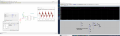
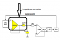
The LTC2203 is a relatively fast 25 Msps ADC.
In the data sheet I can not find any filter capacitors on the analogue inputs above 100 pF, most sketches have capacitors down in the 5 to 12 pF range.
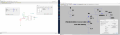
The LTC2203 is a relatively fast 25 Msps ADC.
In the data sheet I can not find any filter capacitors on the analogue inputs above 100 pF, most sketches have capacitors down in the 5 to 12 pF range.