SUCCESS STORIES: Repair thermoelectric cooler

MrChips

Joined Oct 2, 2009
35,278
We need to get someone to measure the voltage at IC1 TL494, Vcc, pin-12.
C8 is listed as 47μF 25V. Perhaps C8 should be replaced with a capacitor with a higher voltage rating, 50V or 63V.
 

Thread Starter

wayneh

Joined Sep 9, 2010
18,181
FWIW, I don't think there's an example here of a successful repair that has since also failed. I made an effort to source a quality part for my C8 repair. I don't know about the other successes here but I'd guess most of them were not just the cheapest replacement they could find. So at least part of the problem at C8 seems to be with the capacitors themselves and not entirely bad design specifications.
 
So did the designer make a mistake by not specifying a better C8? Did the designer get second-guessed by the purchasing department, who patted themselves on the back for saving a few pennies by making a "better" choice?

Some may say it's planned obsolescence but I don't buy that. It's my nature to embrace Hanlon's Razor: "Never attribute to malice that which is adequately explained by stupidity." I think stupidity is a far more likely explanation than any evil plan.
It's certainly possible the designer made a mistake - especially for electrolytic capacitors, which are rated in such a manner that they "seem" fine unless you do the math. For instance, in a system that only gets "warm", component temperature ratings are generally not a concern, except for electrolytic capacitors. Even a cheap capacitor will typically be rated for 85 degrees, which seems like it should have lots of margin until one reads the fine print and discovers the lifetime is only 1000 hours at this temperature! I know it was a surprise to me as a young designer long ago when I saw that components were specified with such low lifetimes (hard to imagine an application where 1000 hours is sufficient!). Once the derating for temperature and working voltage are applied one discovers that the lifetime is far less than expected.
 

MisterBill2

Joined Jan 23, 2018
28,502
While engineers design equipment to a specified quality level, in some organizations the purchasing group has the ultimate final choice. Unfortunately that final choice is made based on purchase price and not suitability for the application. Sp in those instances, with the choice being made by individuals with no technical qualifications at all, selections based on price win. Then the engineer is blamed when warranty costs climb.
The worst case then is when a whole board of directors are all accounting types who only see $$$$.
 

joe NOLA

Joined Dec 14, 2023
1
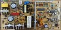
Thanks to all you have contributed to this thread. My Wine Enthusiast 48 bottle duel zone finally bit the dust. One side completely stopped and the other is on it's last breath. I changed C8 on the bad side and it was OK except the fan speeds were not right. I changed all the caps and seems to be working fine although a little cooler than the setting. I'm waiting on parts for the other side. I've attached a photo of my board and capacitor specs since I didn't see any info here for an FX-100-1 PCB.

Can anyone tell me how the red and green LED's should "act"? Since the the problems started they've been all over the place.

Thanks again for making all this info available.
 

Attachments

heat24

Joined Dec 28, 2023
1
I have a Cuisinart CWC-1600 with Hanyi board 0757-83835018. I found the very helpful post by Mr Chips summarizing different boards (https://forum.allaboutcircuits.com/threads/how-to-repair-a-thermoelectric-wine-cooler.176296/) but don't see my model there or the Cuisinart unit. Does anyone know of a compatible replacement board for the 83835018? I just want to swap in a new board if there's one for a reasonable price. I don't want to troubleshoot and replace individual components (the board makes a high pitched noise when plugged in and probably has a bad cap or otherwise). Thanks!
 

Ofirshw

Joined Dec 23, 2023
15
Thanks for this amazing resource!

I can report another HYS80-12J with a C8 that has gone bad. Looking at the schematics (thanks!) it's clear why this capacitor is under huge pressure, compared to its size.
The phenomenon in my case was that the wine cooler refused to work under load - the light was blinking and it seems as if it fails to start. Disconnecting the TEC made it work perfectly (but no cooling obviously), which focused the issue around the parts that feeds the beast.
A single C8 replacement did the trick.
Note that in my circuit there was some mismatch in names between the schematics provided here (e.g. D6 is the name of a diode on another part of the circuit), but the region of the TEC seems to have the same connectivity and component types and values.

Thank you for this fantastic forum!
 

rdkozlow

Joined Jan 30, 2024
1
I have a ten year old Wine Enthusiast 24 bottle dual zone that crapped out recently. I found this thread through a search on Google and thankfully I did. I replaced C8 on the suspect FX-101 board and it's running like a champ again. Many thanks to all who contributed to this thread; you saved me a lot of time and money!
 
My Emerson FR24SL 8 bottle wine cooler went kaput about a year ago. I found this forum thread and successfully got it up and running by replacing the C8 capacitor. All was fine until just recently I noticed the unit was again no longer cooling. I thought the C8 might have been the problem again but this time, no clicking, or squealing, the display works fine and the LEDs appeared to be functioning normally. So I checked this thread again and based on the information, I gleaned that the TEC was might be the problem. Checked power to the TEC and it seemed fine. I then disconnected the TEC and checked resistance which was approximately 140 ohms (expected it to be around 3 OHMs). Pulled the cooling unit removed the TEC-12-12075 and based on a youtube video checked the cooling/heating using a 9 volt battery. The battery test showed very little temperature difference between the two sides judging by feel. I ordered two replacements (TEC-1 12076 for $9.99) some conductive paste (Arctic MX-4 for $5.38) and a Kizen IR thermometer ($13.79) from Amazon. The IR thermometer is really handy. It confirmed the bad TEC, verified the new TECs and it will be a handy tool for future troubleshooting. My wine cooler is back up and running again. Thanks to all the help from this forum thread.
 
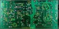
I had the same problem but replacing the Caps didn't solve the problem for me. I reverse engineered the PCB to build a new one with (mostly) new components. If someone else comes across this thread; the gerber files can be found attached here. Included is a BOM with part numbers for Mouser and Digikey.

There are a few important steps to follow though:

1. On the bottom side of the original PCB there are some additionaly tinned up tracks. This is sometimes done where PCB-tracks are too narrow for the expected amount of electricity. I did adopt this 1:1 without checking whether it is really required. Before assembling any part of the PCB you should tin up these tracks, too.

2. I kept the Component designators the same as on the original board. It didn't make much sense to me there, so don't expect to find a continuous numbering here.

3. There is a 74.2kΩ resitor (R211) on the original board. Resistors of this value can be difficult to get at times, so I added the option to use two seperate resitors of 68kΩ and 6.2kΩ respectively (R211:A and R211:B). Only populate either the R211 resitor or the two R211:A/R211:B resistors. Do not populate all three of them!

4. You will need to reuse the two transformers TR1 & TR2 (labelled as "JBC-983-EEL-19" and "MP-011/220V" or "MP012-110V" (depending on where you are in the world)) as well as the three heatsinks.

5. The two Fuses (F1 & F2) need to be protected from accidentally shorting to other parts by enclosing them in heat shrink tubing of an appropriate size.

All the files and information provided here are provided free of charge with NO WARRANTY WHATSOEVER. Working with electronics is dangerous and can be lethal. You and only you are responsible for any damage and/or injuries by any use of the files and/or information given here!
 

Attachments

MisterBill2

Joined Jan 23, 2018
28,502
Building a whole new board is what I would call a rather extreme effort. Testing individual components and replacing those that were questionable, on the same PCB would be simpler and cheaper. My approach has been to understand how the devices is supposed to function, how it does function, and then evaluate the items that would logically cause the malfunction.
Certainly your approach would work, and evidently it did.
Thanks for sharing so that others may learn.
 
I had the same problem but replacing the Caps didn't solve the problem for me. I reverse engineered the PCB to build a new one with (mostly) new components. If someone else comes across this thread; the gerber files can be found attached here. Included is a BOM with part numbers for Mouser and Digikey.

There are a few important steps to follow though:

1. On the bottom side of the original PCB there are some additionaly tinned up tracks. This is sometimes done where PCB-tracks are too narrow for the expected amount of electricity. I did adopt this 1:1 without checking whether it is really required. Before assembling any part of the PCB you should tin up these tracks, too.

2. I kept the Component designators the same as on the original board. It didn't make much sense to me there, so don't expect to find a continuous numbering here.

3. There is a 74.2kΩ resitor (R211) on the original board. Resistors of this value can be difficult to get at times, so I added the option to use two seperate resitors of 68kΩ and 6.2kΩ respectively (R211:A and R211:B). Only populate either the R211 resitor or the two R211:A/R211:B resistors. Do not populate all three of them!

4. You will need to reuse the two transformers TR1 & TR2 (labelled as "JBC-983-EEL-19" and "MP-011/220V" or "MP012-110V" (depending on where you are in the world)) as well as the three heatsinks.

5. The two Fuses (F1 & F2) need to be protected from accidentally shorting to other parts by enclosing them in heat shrink tubing of an appropriate size.

All the files and information provided here are provided free of charge with NO WARRANTY WHATSOEVER. Working with electronics is dangerous and can be lethal. You and only you are responsible for any damage and/or injuries by any use of the files and/or information given here!
Great work. Would you care to include the schematics and layout too?
 

asel51

Joined May 13, 2024
3
I have the same cooler and the power supply was not switching. I replaced all the electrolytic caps and it works again. Thanks for all the previous comments.
 

MrChips

Joined Oct 2, 2009
35,278
I have the same cooler and the power supply was not switching. I replaced all the electrolytic caps and it works again. Thanks for all the previous comments.
Good to hear that you got it working. Too bad you replaced all the caps at once. It would have been useful to know which one was causing the problem.
 

asel51

Joined May 13, 2024
3
Good to hear that you got it working. Too bad you replaced all the caps at once. It would have been useful to know which one was causing the problem.
Agreed, but it was quicker to just replace all than to do one, test, do another, test, etc. I suspect it was the one
Good to hear that you got it working. Too bad you replaced all the caps at once. It would have been useful to know which one was causing the problem.
True, but it was just quicker to replace all rather that one at a time with testing in between.
 

asel51

Joined May 13, 2024
3
Good to hear that you got it working. Too bad you replaced all the caps at once. It would have been useful to know which one was causing the problem.
Agreed, but it was quicker to just replace all than to do one, test, do another, test, etc. I suspect it was the one or several around the transformers as the converter was not switching.
 

Vtince

Joined Jul 2, 2024
1
Alright this forum has helped me so much. I gave a Kalamera KR-28ASS wine cooler that has an MP-012 board. When I got it it wasn’t working and the board had the red and green led lowly lit and flickering and making a staticky noise. Fans were not running and the front temp control display was not working.

I replaced all the capacitors except for the 2 large 200V 120uf ones (should I replace these?). Now the wine fridge is working, the fans are running and the front display is working also.

I set the temp to 55 on the display and let the fridge cool, when the temp gets close to that value I hear the fan slow down, and when I look at the board, the red led is pulsing bright to dim, and the green led is blinking on/off. Is this normal? (Also if the ambient light is turned on on the inside of the fridge, it will flicker slightly also when the fan is slowed)

Another thing I noticed is that the display reads at least 10degrees cooler that inside the fridge. Is there a way to calibrate/fix this? Since if I set to 55, the fridge will stop cooling and the inside is actually at 65.
 

MrChips

Joined Oct 2, 2009
35,278
Alright this forum has helped me so much. I gave a Kalamera KR-28ASS wine cooler that has an MP-012 board. When I got it it wasn’t working and the board had the red and green led lowly lit and flickering and making a staticky noise. Fans were not running and the front temp control display was not working.

I replaced all the capacitors except for the 2 large 200V 120uf ones (should I replace these?). Now the wine fridge is working, the fans are running and the front display is working also.

I set the temp to 55 on the display and let the fridge cool, when the temp gets close to that value I hear the fan slow down, and when I look at the board, the red led is pulsing bright to dim, and the green led is blinking on/off. Is this normal? (Also if the ambient light is turned on on the inside of the fridge, it will flicker slightly also when the fan is slowed)

Another thing I noticed is that the display reads at least 10degrees cooler that inside the fridge. Is there a way to calibrate/fix this? Since if I set to 55, the fridge will stop cooling and the inside is actually at 65.
This thread is for success stories only. Please start a new thread.
 
Thread starter Similar threads Forum Replies Date
SgtWookie Off-Topic 4
Top