Facebook
 Google
 GitHub
 Linkedin

Hi,
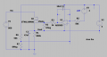
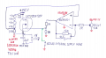
I am building a regulated high voltage power supply for photomultipliers. Idea is that I generate fixed clean 880V DC and then I can regulate it down to whatever voltage I want via software. For that I am using one high voltage MOSFET and I turn it on just as much, so its source's voltage match my target voltage - MOSFET is essentially used as a voltage controlled resistor. This approach is suitable for me, since average opearating current is bellow 1 mA, and switching characteristics of OSFET are irrelevant (transitions seconds long are acceptable). I have an appropriate high voltage resistive divider across drain source junction to sense, how much voltage is being dropped across MOSFET itself. That sense pin is connected to MCP6001 opamp, another input is hooked to digital potentiometer to set wanted reference level (control MOSFET operation). It's very important to mention that MCP6001, AD5241 and the whole sensing network is not referenced to true system ground, but rather a MOSFET's source - I essentially have a floating gate drive network. You can see everything in the schematic diagram I attach bellow.
This circuit works partially. I do get corresponding high voltage regulation according to reference voltage that I program. I get clean DC ramp, clean MCP6001 ouput, both inputs of the opamp are driven equally etc. The fundamental problem I face is that there is a voltage ceiling around 780V (Source to true GND) that I bump into when trying to turn the MOSFET on entirely. Myopamp output is verified to be clean 3.8V DC (Gate to source) in such case when digital potentiometer is set to its boundary value. At first I thought that 3.8V is not enough to fully turn on my MOSFET, but after plugging a standard DC lab supply to gate source junction, I verified that even 3.3V was enough to fully turn on my MOSFET - source potential became exactly 880V (with negligible losses). Since I am sure that my opamp ouput reaches 3.8V while driving the gate, I do not understand the problem why is the opamp not turning my MOSFET on hard enough? We are talking about low currents and effectively no switching, so I can not believe that MCP6001 output lacks current to charge the MOSFET's junction even during multiple seconds. I hope I provided enough information and details about this strange problem. Any help or observations are highly appreciated. I thank you in advance.
I am building a regulated high voltage power supply for photomultipliers. Idea is that I generate fixed clean 880V DC and then I can regulate it down to whatever voltage I want via software. For that I am using one high voltage MOSFET and I turn it on just as much, so its source's voltage match my target voltage - MOSFET is essentially used as a voltage controlled resistor. This approach is suitable for me, since average opearating current is bellow 1 mA, and switching characteristics of OSFET are irrelevant (transitions seconds long are acceptable). I have an appropriate high voltage resistive divider across drain source junction to sense, how much voltage is being dropped across MOSFET itself. That sense pin is connected to MCP6001 opamp, another input is hooked to digital potentiometer to set wanted reference level (control MOSFET operation). It's very important to mention that MCP6001, AD5241 and the whole sensing network is not referenced to true system ground, but rather a MOSFET's source - I essentially have a floating gate drive network. You can see everything in the schematic diagram I attach bellow.
This circuit works partially. I do get corresponding high voltage regulation according to reference voltage that I program. I get clean DC ramp, clean MCP6001 ouput, both inputs of the opamp are driven equally etc. The fundamental problem I face is that there is a voltage ceiling around 780V (Source to true GND) that I bump into when trying to turn the MOSFET on entirely. Myopamp output is verified to be clean 3.8V DC (Gate to source) in such case when digital potentiometer is set to its boundary value. At first I thought that 3.8V is not enough to fully turn on my MOSFET, but after plugging a standard DC lab supply to gate source junction, I verified that even 3.3V was enough to fully turn on my MOSFET - source potential became exactly 880V (with negligible losses). Since I am sure that my opamp ouput reaches 3.8V while driving the gate, I do not understand the problem why is the opamp not turning my MOSFET on hard enough? We are talking about low currents and effectively no switching, so I can not believe that MCP6001 output lacks current to charge the MOSFET's junction even during multiple seconds. I hope I provided enough information and details about this strange problem. Any help or observations are highly appreciated. I thank you in advance.
Attachments
-
 117.5 KB Views: 16