Facebook
 Google
 GitHub
 Linkedin


Hello All,
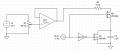
I am trying to build a resettable op-amp integrator for a timing circuit in a sequencer. The Integrator is supposed to output a ramp, which is reset to zero at regular intervals. I want the reset to happen as quickly as possible. When using the 2N7000 for the reset switch with an on-resistance of 5 Ohms and a 1 µF cap, I get a time constant of 5 µs, so a discharge time of \[ 5 \cdot \tau = 25 \, \mu s \] However, the discharge curve of the capacitor does not look as expected and it takes much longer than 25 µs to settle at a fixed voltage, more like 15 ms. To isolate this and to rule out any influence of the op-amp, I built a simple testing circuit as seen below. C1 gets charged in the HIGH-phase of the clock and discharged in the LOW-phase, via the FETs.
 Below you can see oscilloscope screenshots of the cap voltage (green) and the M2 gate voltage (blue). Please excuse my bad phone camera.
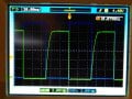 As you can see the circuit works in principle. But when zooming in on the bottom of the discharge, there is some ringing going on, which is much slower than what I would expect from the RC time constant I calculated. At first the discharge seems to be as quick as expected, but then, at about 220 mV, some other more dominant effect takes over. Then it takes about 15 ms to arrive at a steady state.
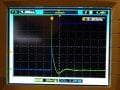
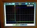
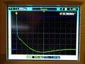 Then, also the intensity of this effect is influenced by the voltage the capacitor has been charged to before discharge. Above pictures are for 10 V. If I trim pot R1, so the cap is only charged to 5V, it is much less prominent, as can be seen in the picture below.
 I thought it may be some non-linearity in the capacitor (greater capacitance for lower voltages?). However, the same thing happens if I completely remove the capacitor from the circuit. I also replaced the reset MOSFET with a HE3321 reed relay, to rule out some strange MOSFET behavior, but still the exact same result. So if it is not the cap and not the FET, my assumption now would be, that I got some kind of parasitic resonant circuit in my design, but I can't figure where or why. I am prototyping this on a breadboard, could this cause such a thing? How could I proceed to find the source of this ringing? Any help would be greatly appreciated, as this is kind of a road block for my project and I am out of my depth here. Thanks for reading

I am trying to build a resettable op-amp integrator for a timing circuit in a sequencer. The Integrator is supposed to output a ramp, which is reset to zero at regular intervals. I want the reset to happen as quickly as possible. When using the 2N7000 for the reset switch with an on-resistance of 5 Ohms and a 1 µF cap, I get a time constant of 5 µs, so a discharge time of \[ 5 \cdot \tau = 25 \, \mu s \] However, the discharge curve of the capacitor does not look as expected and it takes much longer than 25 µs to settle at a fixed voltage, more like 15 ms. To isolate this and to rule out any influence of the op-amp, I built a simple testing circuit as seen below. C1 gets charged in the HIGH-phase of the clock and discharged in the LOW-phase, via the FETs.