Strange behavior of clock circuit

Thread Starter

freak101

Joined Aug 7, 2017
37
Hello,

After going through couple of tutorials of ben eater on youtube, I decided to brew my own 8-bit computer.
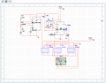
However, the clock circuit is showing a strange behavior.
The clock circuit consists of a 555 in astable mode and another 555 in monostable mode which debounces a pushbutton.
A digital logic circuit is also used which has a select line that selects two of the above sources. It consists of not,and and or gates (all 74 series). A logic high on select line selects astable mode while logic low selects monostable mode.
Now the problem is that when select line goes high, the output of logic gates is constantly high (instead of that blinking). When select line is low, everything works well.
I am very much aware that one should never take a logic signal off an output that is already driving an LED.
However, I connected a led to output of astable mode 555. I am seeing that it goes dim and stops blinking when select line goes high.
Looks like problem is pretty obvious but I cannot figure out what it is.

Thanx for your help !
 

smooth_jamie

Joined Jan 4, 2017
107
Why don't you swap the 555 debounce for a simple RC circuit (something like the one below)? This will help you simplify the circuit.

Next place a switch on the select Vcc line so you can pulse it without changing the potential of Vcc in your simulation, and see if it acts differently.


Thread Starter

freak101

Joined Aug 7, 2017
37
Why don't you swap the 555 debounce for a simple RC circuit (something like the one below)? This will help you simplify the circuit.
But the current debounce circuit works fine. Its just that when select line goes high, the output from logic gate stays high, output of astable mode 555 goes pretty low (and blinking is not observable) and monostable mode 555 stops working.
 

ericgibbs

Joined Jan 29, 2010
18,872
hi 101,
It is still showing two outputs linked together, as per my post #5, U2, Q2 output connected to A2 [555] Output.
Do you really want to link two outputs.?
Could you add pin numbers to the 7408's so I can be sure what I am looking at.?

E
 

smooth_jamie

Joined Jan 4, 2017
107
Just checking your schematic. Vcc on U1, U2, and U3 are tied together but they aren't actually connected to Vcc? Is this correct or have I missed something?
 

dl324

Joined Mar 30, 2015
16,943
That Vcc (lower right) is actually select line which I change from Vcc to ground manually.
A slightly easier to read version of the original schematic:
upload_2018-1-11_7-19-46.png

BTW, your schematic drawing skills are abysmal. Too many unnecessary wire jogs, ground should always point down, inconsistent use of connection dots, wires/components overlapping designators/values, erratic flow, intent obscured by using "IC" style components (this one is Multisim's fault), ...

If I didn't make any transcription errors, this is what you drew:
upload_2018-1-11_7-21-4.png

What is the purpose of using gates that have their inputs tied HIGH?

One caution regarding Multisim. It's very easy to have things looked like they're connected when in reality they aren't. When circuits didn't work as expected, I got into the habit of grabbing components and moving them around to make sure the wires were really attached the way I thought they were.
 

Thread Starter

freak101

Joined Aug 7, 2017
37
Thank you so much for your efforts dl324. Its normally not easy to decode my schematics !
Those high inputs to logic gate is actually select line. I should have expressed myself clearly in first post itself. Sorry.
The original series uses a dpdt switch with 555 in bistable mode which acts as its debouncer. This bistable 555 is actually select line.
Now my local electronics store had no dpdt switch on it (I have ordered them from ebay now). So as a temporary workaround, I am putting my select line high DIRECTLY and this accounts for those directly connected high inputs. I am using a jumper wire for select line and I connect it to ground "on the fly" whenever I want to switch to monostable mode (i.e a clock pulse occurs only when I push the button).
Hope it clarifies things.
 

dl324

Joined Mar 30, 2015
16,943
It is connecting A2 output to the 2Q output of U2.
They seemed to use TI nomenclature; the Y's are outputs. The things that people are calling Q's are actually B's.
upload_2018-1-11_8-45-18.png

The original drawing didn't help... The dots make the B's look like Q's with the tail on the wrong side.
upload_2018-1-11_8-47-29.png
 

dl324

Joined Mar 30, 2015
16,943
Its normally not easy to decode my schematics !
Challenge yourself to draw more readable schematics. You'll be less likely to be embarrassed by your workmanship.

Multisim has some generic gates that you could have used to convey the select functionality more clearly.
as a temporary workaround, I am putting my select line high DIRECTLY and this accounts for those directly connected high inputs. I am using a jumper wire for select line and I connect it to ground "on the fly" whenever I want to switch to monostable mode
Multisim allows you to have many switches using different keys to select them.

But why are you simulating such a simple circuit? That's akin to using a calculator to add 12+34.
 
Top