stepper motor driver help

Thread Starter

stylediva

Joined Dec 6, 2011
72
i have a unipolar stepper motor.its specifications are TYPE:23LM-C701-01 , N/P: RH7-1048 04 , 5.2V/PHASE , 1.4 A/PHASE, 1.8 DEG/PHASE...
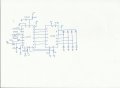
i have made the l297/l298 stepper motor driver which is shown in the datasheet of l297..
http://www.soiseek.com/STMICROELECTRONICS/L298/

reset=1
clock=PWM
H/F=0
CCW/CW=1
vs=12v
vref=0.5v
Sense resistor=0.5 ohm

but its not working..when i check that l298 gets warm and the motor is not working..can anyone help me with this??..
 

DickCappels

Joined Aug 21, 2008
10,661
Are you clocking the input of the L1297 and getting the right outputs from that?

What are the voltages that you measure on the various pins of the I298?
 

Thread Starter

stylediva

Joined Dec 6, 2011
72
i m getting '0' at output pins of l298..what should be the outputs at l297??...l298 gets warm before i test every output..
 

shortbus

Joined Sep 30, 2009
10,050
Your clock signal should not be a PWM signal. It should just be a steady pulse from an astable oscillator, like a 555.
 

SgtWookie

Joined Jul 17, 2007
22,230
The L298 will drop about 4v across its' high and low sides when it is passing 1.5A; that's 6W. If you're using both H-bridges, that's 4v * 1.5A * 4 = 24W; you'll burn it up mighty quickly unless you have the L298 solidly attached to a LARGE heat sink.
 

SgtWookie

Joined Jul 17, 2007
22,230
The L297 and L298 should be wired in a "chopper driver" configuration. You use a much higher supply voltage than the stepper is rated for - but of course, you have to stay about 10% below the rating of the L298.

The datasheet for the L297 has lots of info on how to use the chopper driver feature. But, without knowing your stepper motor's current rating, resistance, or voltage rating, we won't be of much help in figuring out what voltage you need at Vref.
 

Thread Starter

stylediva

Joined Dec 6, 2011
72
sir i have attached the specifications of my motor..plz guide me what is the problem..when i check my driver without any load then it is ok..but when i attached the motor then the ground and supply becomes short and sparking is seen on the battery..and the motor does not move..plz tell me what to do..:(
 

Attachments

Thread Starter

stylediva

Joined Dec 6, 2011
72
current rating is 1A for bipolar..sense resistor=0.5 ohm..so vref=I*R=0.5v
i have set this value at 15 pin of L297..vs=12v..is is ok??..
 

shortbus

Joined Sep 30, 2009
10,050
sir i have attached the specifications of my motor..plz guide me what is the problem..when i check my driver without any load then it is ok..but when i attached the motor then the ground and supply becomes short and sparking is seen on the battery..and the motor does not move..plz tell me what to do..:(
How are you wiring the motor? in your next post you say "bipolar". If wiring the motor bipolar you would ignore the "white and black" wires. Just make sure that the ends are taped but not connected to each other.
 

Thread Starter

stylediva

Joined Dec 6, 2011
72
i have attached the schematic..
CW/CCW=0
HALF/FULL=0
RESET=1
CLOCK=pwm from AVR atmega16..
diodes are fast recovery diodes 2A..
pin 2,3,13,14 are connected to the coils of stepper..Black and white are left unconnected..
 

Attachments

shortbus

Joined Sep 30, 2009
10,050
The clock is NOT to be a PWM signal! It should only be a pulse of over two volt, What is the output voltage of the atmega16?
 

Thread Starter

stylediva

Joined Dec 6, 2011
72
i have taken pwm signal from my controller..it shows 2.5v for HIGH and 0 for LOW..i have also checked my circuit with the HIGH LOW pulses in a loop..i made one pin of my controller HIGH and after some delay i have made that LOW..but still the circuit is not working and the supply and ground becomes short..
 

shortbus

Joined Sep 30, 2009
10,050
Are you doing this on a 'breadboard' or a PCB?

If on a breadboard, are all connections sound and no loose ones?

If on a PCB check closely to see if there are any 'solder bridges' between traces. Or 'cold' joints not making good contact electrically.

Also try switching the L297 with another one, you may have damaged this one. It happens :)
 

Thread Starter

stylediva

Joined Dec 6, 2011
72
i am doing it on vero board..i have done this two times but both the drivers are not working..black and white wires are left unconnected..what is the mistake that i m doing..is the schematic right??..when i connect motor then the resistance between supply and ground becomes so low and it shorts..
 
Top