 Facebook
 Google
 GitHub
 Linkedin
Hi everyone.
I have been facing the issue to run the Bipolar stepper motor using the TB6612 Stepper Motor Driver Breakout Board. On the internet there are many codes available regarding controlling the stepper motor by changing the RPM ,but my motor is working on PPS (Pulse per seconds). i took the code from the ad fruit website to run the motor.
https://learn.adafruit.com/adafruit...er-motor-driver-breakout/using-stepper-motors
the code is
but this code didn't work, the company from where i bought the pump having stepper motor provide me one page regarding the flow rate controlling of pump and they also provide me the method how to control the flow rate.
**the method is**
" How It Works:
・The stepper motor has two sets of wires connected to two coils inside the motor.
・We call these coils "Coil A" and "Coil B".
Coil A is controlled by two wires (Black and Brown).
Coil B is controlled by another two wires (Orange and Yellow).
Operating the Motor:
The motor works by turning on these coils in a specific sequence.
First, Coil A is turned on, which moves the motor a little bit.
Then Coil B is turned on, which moves the motor a bit more.
By continuing to switch between these coils in a pattern, the motor rotates smoothly.
Controlling the Speed (and Flow Rate):
・Faster Pulses = Faster Motor = Higher Flow Rate: If we send pulses quickly, the motor turns faster, which pumps the fluid faster.
・Slower Pulses = Slower Motor = Lower Flow Rate: If we send pulses more slowly, the motor turns slower, reducing the flow rate."
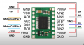
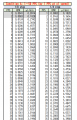
the Flow rate related file is attached in the picture. Also, the pin configuration is correct as per my understanding, and pin configuration is also attached in the picture as well.
the motor worked on 10V DC which i applied on Vm pin of the module and the current draw by it is 350mA. With different codes the pump even didn't turn ON and i didn't listen or see any voice of the pump
few things i observed.
when i gave the 10vDC to Vm pin of the TB6612 Stepper Motor Driver Breakout Board, without connecting it with Arduino, the multimeter shows the 10V DC across , but when i connected the Arduino to Vcc of this board the voltage drop down to 1.14, Also the pins of the board used to connect with the coil of the motor shows the DC voltage 0, the board picture is also attached below, Motor A two pins used for one pair of motor coil and Motor B 2 pins used for second coil of stepper motor
my questions are.
1) can someone provide me the code to control the flow rate using the PPS method, i saw few codes using the AI tool but no one is working.
2) does in case of controlling the flow rate using the PPS does we need to change the pins configuration or not.
3) does this pump will work by changing the RPM or we have to control the flow rate using the PPS method
I have been facing the issue to run the Bipolar stepper motor using the TB6612 Stepper Motor Driver Breakout Board. On the internet there are many codes available regarding controlling the stepper motor by changing the RPM ,but my motor is working on PPS (Pulse per seconds). i took the code from the ad fruit website to run the motor.
https://learn.adafruit.com/adafruit...er-motor-driver-breakout/using-stepper-motors
the code is
Arduino Code:
#include <Stepper.h>

// change this to the number of steps on your motor
#define STEPS 200

// create an instance of the stepper class, specifying
// the number of steps of the motor and the pins it's
// attached to
Stepper stepper(STEPS, 4, 5, 6, 7);


void setup()
{
  Serial.begin(9600);
  Serial.println("Stepper test!");
  // set the speed of the motor to 30 RPMs
  stepper.setSpeed(60);
}

void loop()
{
  Serial.println("Forward");
  stepper.step(STEPS);
  Serial.println("Backward");
  stepper.step(-STEPS);
}**the method is**
" How It Works:
・The stepper motor has two sets of wires connected to two coils inside the motor.
・We call these coils "Coil A" and "Coil B".
Coil A is controlled by two wires (Black and Brown).
Coil B is controlled by another two wires (Orange and Yellow).
Operating the Motor:
The motor works by turning on these coils in a specific sequence.
First, Coil A is turned on, which moves the motor a little bit.
Then Coil B is turned on, which moves the motor a bit more.
By continuing to switch between these coils in a pattern, the motor rotates smoothly.
Controlling the Speed (and Flow Rate):
・Faster Pulses = Faster Motor = Higher Flow Rate: If we send pulses quickly, the motor turns faster, which pumps the fluid faster.
・Slower Pulses = Slower Motor = Lower Flow Rate: If we send pulses more slowly, the motor turns slower, reducing the flow rate."
the Flow rate related file is attached in the picture. Also, the pin configuration is correct as per my understanding, and pin configuration is also attached in the picture as well.
the motor worked on 10V DC which i applied on Vm pin of the module and the current draw by it is 350mA. With different codes the pump even didn't turn ON and i didn't listen or see any voice of the pump
few things i observed.
when i gave the 10vDC to Vm pin of the TB6612 Stepper Motor Driver Breakout Board, without connecting it with Arduino, the multimeter shows the 10V DC across , but when i connected the Arduino to Vcc of this board the voltage drop down to 1.14, Also the pins of the board used to connect with the coil of the motor shows the DC voltage 0, the board picture is also attached below, Motor A two pins used for one pair of motor coil and Motor B 2 pins used for second coil of stepper motor
my questions are.
1) can someone provide me the code to control the flow rate using the PPS method, i saw few codes using the AI tool but no one is working.
2) does in case of controlling the flow rate using the PPS does we need to change the pins configuration or not.
3) does this pump will work by changing the RPM or we have to control the flow rate using the PPS method
Attachments
-
 443.2 KB Views: 7
 -
 121.1 KB Views: 7
 -
 128.6 KB Views: 5
Last edited by a moderator:


