 Facebook
 Google
 GitHub
 Linkedin
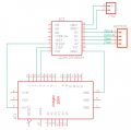
I have a bipolar stepper motor that I want to run using the DRV8834 Dual-Bridge Stepper Motor Driver. The connection schematic is correct (I followed another post) and is attached in the picture.
The resistance of both motor coils is 11Ω (measured with a multimeter). I supplied 10V DC to the Vm pin of the DRV8834 using a Keithley Triple Channel DC Power Supply (30V, 1.5A).
When I upload the code below and run the motor, it only produces a low noise. The code is attached below
The current drawn by the motor is 0.90A (10V / 11Ω), and I set the current limit of the driver to 0.45A using the formula:
Current Limit= ref × 2
I connected a 100μF capacitor between the Vm+ pin and the Ground pin.
The problem is that when I upload the code, the motor only generates noise and does not rotate. I am confused about why it’s not rotating and is only producing noise.
The working operation of the motor, as provided by the company:
Operating the Motor:
The motor works by turning on these coils in a specific sequence.
First, Coil A is turned on, which moves the motor a little bit.
Then, Coil B is turned on, which moves the motor a bit more.
By continuing to switch between these coils in a pattern, the motor rotates smoothly.
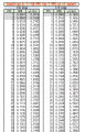
Controlling the Speed (and Flow Rate):
Faster Pulses = Faster Motor = Higher Flow Rate: If we send pulses quickly, the motor turns faster, which pumps the fluid faster.
Slower Pulses = Slower Motor = Lower Flow Rate: If we send pulses more slowly, the motor turns slower, reducing the flow rate.
The flow rate-related file is attached in the picture.
Voltage Measurements:
After uploading the code and during the noise/buzz generated by the motor, the DC voltage across Coil A shows:
One wire: 1.9V
The second wire: 0.65V
For Coil B:
One wire: 1.9V
The second wire: 0.67V
Can someone help me sort out this issue, i failed to run the stepper motor?, the required pictures are attached below.
Your assistance would be greatly appreciated.
The resistance of both motor coils is 11Ω (measured with a multimeter). I supplied 10V DC to the Vm pin of the DRV8834 using a Keithley Triple Channel DC Power Supply (30V, 1.5A).
When I upload the code below and run the motor, it only produces a low noise. The code is attached below
Arduino Code:
#include "AccelStepper.h"
#define dirPin 2
#define stepPin 3
#define motorInterfaceType 1

// Create a new instance of the AccelStepper class:
AccelStepper stepper = AccelStepper(motorInterfaceType, stepPin, dirPin);

void setup() {
  // Set the maximum speed in steps per second:
  stepper.setMaxSpeed(1000);
}

void loop() {
  // Set the speed in steps per second:
  stepper.setSpeed(400);
  // Step the motor with a constant speed as set by setSpeed():
  stepper.runSpeed();
}Current Limit= ref × 2
I connected a 100μF capacitor between the Vm+ pin and the Ground pin.
The problem is that when I upload the code, the motor only generates noise and does not rotate. I am confused about why it’s not rotating and is only producing noise.
The working operation of the motor, as provided by the company:
Operating the Motor:
The motor works by turning on these coils in a specific sequence.
First, Coil A is turned on, which moves the motor a little bit.
Then, Coil B is turned on, which moves the motor a bit more.
By continuing to switch between these coils in a pattern, the motor rotates smoothly.
Controlling the Speed (and Flow Rate):
Faster Pulses = Faster Motor = Higher Flow Rate: If we send pulses quickly, the motor turns faster, which pumps the fluid faster.
Slower Pulses = Slower Motor = Lower Flow Rate: If we send pulses more slowly, the motor turns slower, reducing the flow rate.
The flow rate-related file is attached in the picture.
Voltage Measurements:
After uploading the code and during the noise/buzz generated by the motor, the DC voltage across Coil A shows:
One wire: 1.9V
The second wire: 0.65V
For Coil B:
One wire: 1.9V
The second wire: 0.67V
Can someone help me sort out this issue, i failed to run the stepper motor?, the required pictures are attached below.
Your assistance would be greatly appreciated.
Attachments
-
 121.1 KB Views: 4
 -
 6.4 KB Views: 4


