It's progress, but it can be frustrating trying to keep up.
A couple centuries ago one intelligent person could pretty well know all the human accumulated technical knowledge available.
From there the knowledge grew exponentially so that now one person can know only a very tiny fraction of the total.
It's progress, but it can be frustrating trying to keep up.
A couple centuries ago one intelligent person could pretty well know all the human accumulated technical knowledge available.
From there the knowledge grew exponentially so that now one person can know only a very tiny fraction of the total.
yeah, aint easy.
sorry to bother u again but...
ur pwm cct. its only good for 1 in 4 quadrature positions, when stationery.
A & B high = pwm to both sides of stepper bridge. all else, gives either pwm 1 side or no pwm.
can u fix?
yeah, aint easy.
sorry to bother u again but...
ur pwm cct. its only good for 1 in 4 quadrature positions, when stationery.
A & B high = pwm to both sides of stepper bridge. all else, gives either pwm 1 side or no pwm.
can u fix? if u got time that is
by the way, finally did test to see mode of op. Full stepping. my theory obviously wrong (dont u hate that!). so now have to find waveforms for ½ stepping, then figure out how to convert quadrature to provide it.
I have no ideas on how that should be implemented on my bridge..
i do know it uses bridge to short out windings between steps= slow decay
& dump windings, reversed, via bridge to rails = fast.
but i'll hazard a guess that if i arent using either modes the stepper wont be very healthy,
- could explain some of the erratic behaviour at various speeds atm.
ur pwm cct. its only good for 1 in 4 quadrature positions, when stationery.
A & B high = pwm to both sides of stepper bridge. all else, gives either pwm 1 side or no pwm.
can u fix?
A, B are The two quadrature outputs..from the encoder.
you said, earlier,
"The 555 circuit can be common but each phase will require its own R2, C3, D4, and U3, U4, and U5 Schmitt-trigger gates''
which i implemented.
so 1 output for A signal, other for B signal.
also,
see, post #35,
'' Problem is, if the encoder moves at all, 1 change of state, either A or B output, then the stepper motor must follow, so suppression would cause an aberation.
Sorry! Certainly appreciate your input.''
...
forum setup wont let me upload from mob. ph.
will try to do when back home, but a bit puzzled re your Q given the whole thread is re encoder outputs, A & B, the two 90° phase shifted signals being used to drive a two phase stepper bridge, which needs current limiting especually when encoder is stationary.
Anyway, will try a bit harder to clarify all.
if only all this was face to face!
start of series of pics.
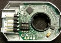
1.This is the encoder guts, 4 switches set o/p for A or B pulse per revs from 48 - 2096!! Not bad for $24
Set to 48 ppr to check easily that it is 48ppr. (index pulse used to confirm).
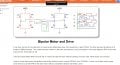
2. Vish2207 posted this A/B driven motor config.
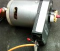
3. Encoder on pony motor with +5v supply, gnd, A out, Bout, Index - 1 rotation = 1 index pulse.
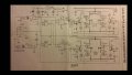
3. schematic with 4013 driving bridge. It was removed so as to feed in A & B pulses & their mirrored states via inverter gates, A & B connection points as marked.
4. schematic bridge only. Input logic deleted. feed in A & B pulses - & their mirrored states fed via inverter gates, (to the bipolar trani's. BC547)
A & B connection points as marked.
posted schematics , encoder etc.. sorry but not sure how forum works..
If i just post a reply, - but not click on reply bottom of your post, do you still get notification?
The Vish2207 copied image, (for which I coludnt find link for earlier when responding via mobile ph.),
shows the basics of what i am doing with the new kit K158 (its actually old, but new to me).
The Vish2207 copied image, (for which I coludnt find link for earlier when responding via mobile ph.),
shows the basics of what i am doing with the new kit K158 (its actually old, but new to me).
here is a graph, & i know every motor different, shows torque vs drive current.
courtesy, Oriental Motors.
so pwm current has a profile that probably, without an MCU determining it, may be very hard to get right with discrete logic or analogue curve generator.
all getting a tad tricky, but i guess if pwm M-S ratio is say 30% on time at zero revs, then climbs to 100% on time at say 250 rpm, then that should be a goer. the trick ist to have a mechanism that either varies the % of pwm vs total pulse width, which the Crutschow cct does do,
or, vary the M-S ratio vs pulse rate.
I suppose there's someone out there that might want both!
Your posted schematics are fine.
So you want the PWM signal to go to the bottom MOSFET only when it is active, not to the top MOSFETs.
Thus the bottom MOSFET signal is disconnected from its gate and used to gate the PWM signal to it.
Thus when a top MOSFET is ON, the opposite-side bottom MOSFET will be receiving the PWM signal.
Make sense?
I can draw my circuit with the needed logic if you want.
(Note that the top P-MOSFETS are incorrectly drawn. The source terminal should go to the plus supply and the drain terminal to the motor.)
the trick ist to have a mechanism that either varies the % of pwm vs total pulse width, which the Crutschow cct does (not) do,
or, vary the M-S ratio vs pulse rate.
I fail to see a good reason to vary the M-S ratio with pulse width.
Why do you think it's needed?
First you adjust the full-on time needed for the highest desired pulse-rate and load (which is determined by how long the mechanical step motion takes).
Then you just select a M-S ratio that works and leave it at that.
@qtron The general theory of stepper drives, as I have always understood it, is the attempt to maintain the rated motor current through the practical rpm range in order to obtain max rpm from the motor, which, if it were supplied with the rated voltage the torque (current) would rapidly drop off due to increasing inductive reactance.
In order to do this, a much higher than plate current is used and the drive regulates the current accordingly.
From your link:
As was mentioned earlier, the speed – torque characteristics are determined by the stepper motor and driver combination. In general, the higher the applied voltage to the motor windings, the faster the motor will rotate. For example, in the curves below, the speed – torque curve for the CVK245AK/CVK245BK stepper driver indicates that 24VDC is applied to the motor windings, while the curve for the RKS545 stepper driver was created with 162VDC being applied to the windings. As you can see, the torque at speed of the RKS545 stepper driver is held out to a much higher speed.
Here's how I would determine the two parameters.
Adjust the P-S ratio to a low value and step the motor that is connected to the desired load with a low frequency (1PPS).
Adjust the turn-on time to the minimum that will generate this step, and then adjust it to about 50% longer than the minimum.
Now set the pulse rate to the maximum desired and adjust the P-S ratio to that it steps correctly.
Your posted schematics are fine.
So you want the PWM signal to go to the bottom MOSFET only when it is active, not to the top MOSFETs.
Thus the bottom MOSFET signal is disconnected from its gate and used to gate the PWM signal to it.
Thus when a top MOSFET is ON, the opposite-side bottom MOSFET will be receiving the PWM signal.
Make sense?
I can draw my circuit with the needed logic if you want.
(Note that the top P-MOSFETS are incorrectly drawn. The source terminal should go to the plus supply and the drain terminal to the motor.)
I fail to see a good reason to vary the M-S ratio with pulse width.
Why do you think it's needed?
You just select a M-S ratio that works at the highest desired pulse-rate and load, and leave it at that.
...
Thankyou for your time, again!
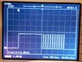
The Last statement first: as i said earlier your circuit varies the % of pwm of total pulse width. As i increase speed the % of PWM in the total pulse falls away to just straight "clean" pulses. Have DSO pics!
At Zero rpm, % of PWM is infinite, ie, just continuous pwm set at the M-S ratio according to pot setting - which is Great!
so no, varying the M-S not needed, unless a very precise curve followed as per graph..
seem to have trouble seeing it tho, I click on "my attachments" selected Go, nothing happened.
..
First part, The PWM is only being applied as you said.
But, the problem is the encoder, at zero revs, stationary, can land on 1 of four states.
so, back to my post #87,
if A & B outputs of the encoder - see two pics posted, are high => pwm to both sides (coil 1, coil 2) of stepper bridge- i mean the two coils are pwm'd. all else,
(sorry didnt mean to imply both sides of the one coil).
all other states of A & B, gives either pwm 1 side, 1 coil, or the other coil, or no pwm. A & B = low (zero volts).
So is there any possibility of a fix ?
Here's how I would determine the two parameters.
Adjust the P-S ratio to a low value and step the motor that is connected to the desired load with a low frequency (1PPS).
Adjust the turn-on time to the minimum that will generate this step, and then adjust it to about 50% longer than the minimum.
Now set the pulse rate to the maximum desired and adjust the P-S ratio to that it steps correctly.
@qtron The general theory of stepper drives, as I have always understood it, is the attempt to maintain the rated motor current through the practical rpm range in order to obtain max rpm from the motor, which, if it were supplied with the rated voltage the torque (current) would rapidly drop off due to increasing inductive reactance.
In order to do this, a much higher than plate current is used and the drive regulates the current accordingly.
From your link:
As was mentioned earlier, the speed – torque characteristics are determined by the stepper motor and driver combination. In general, the higher the applied voltage to the motor windings, the faster the motor will rotate. For example, in the curves below, the speed – torque curve for the CVK245AK/CVK245BK stepper driver indicates that 24VDC is applied to the motor windings, while the curve for the RKS545 stepper driver was created with 162VDC being applied to the windings. As you can see, the torque at speed of the RKS545 stepper driver is held out to a much higher speed.
yes thanks for all Max, had just been reading gecko stuff.
And,
yes saw "RKS545 stepper driver was created with 162VDC being applied to the windings. As you can see, the torque at speed of the RKS545 stepper driver is held out to a much higher speed."
Eyes thought it was a trick, 162V!! must have good winding insulation. Man that thing flies, 3,500 rpm!!
But hey, I think steppers are mongrels!
I thinks, but no experience, that servo's, after PID tuning, are - from reading stuff, much slicker, no mid band shakes etc.
I may be wrong but BLDC motors seem to be easier to drive than steppers.. true?
sad bit: the cost differences
@qtron The general theory of stepper drives, as I have always understood it, is the attempt to maintain the rated motor current through the practical rpm range in order to obtain max rpm from the motor, which, if it were supplied with the rated voltage the torque (current) would rapidly drop off due to increasing inductive reactance.
In order to do this, a much higher than plate current is used and the drive regulates the current accordingly.
From your link:
As was mentioned earlier, the speed – torque characteristics are determined by the stepper motor and driver combination. In general, the higher the applied voltage to the motor windings, the faster the motor will rotate. For example, in the curves below, the speed – torque curve for the CVK245AK/CVK245BK stepper driver indicates that 24VDC is applied to the motor windings, while the curve for the RKS545 stepper driver was created with 162VDC being applied to the windings. As you can see, the torque at speed of the RKS545 stepper driver is held out to a much higher speed.
Your posted schematics are fine.
So you want the PWM signal to go to the bottom MOSFET only when it is active, not to the top MOSFETs.
Thus the bottom MOSFET signal is disconnected from its gate and used to gate the PWM signal to it.
Thus when a top MOSFET is ON, the opposite-side bottom MOSFET will be receiving the PWM signal.
Make sense?
YES!!
(Note that the top P-MOSFETS are incorrectly drawn. The source terminal should go to the plus supply and the drain terminal to the motor.)
.
oops, meant to say,
yes foreign printed schematic thus top FETS a.se about! U not slow! But kit build was ok.
hope this works.. (can see pic in 'my attachments')

 Facebook
 Google
 GitHub
 Linkedin