Motor is 200 steps/Rev, Native. Ie u can feel the steps.
But determining if its stepping 400 steps per Rev, 1/2 stepping, under steam is a bit trickier. Will chew on it.
If I had a means of issueing 400 A/B cycles only from the encoder then I would see 1 Rev of the motor, if its 1/2 stepping.
Rotating the encoder just 1 A/B cycle & then measuring the angular displacement aint so easy. (As per figures quoted earlier, 1 rotation of the encoder is roughly 2.5 motor rotations.
"1641 rpm b4 it crapped out. Encoder was ~ 672 rpm."
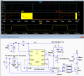
Here's the simulation for a PWM frequency of ≈13kHz with a gate driver consisting of three CD4049 gates in parallel (1/2 package).
Thus it requires just one CD4093 and one CD4049 package for two motor phases.
The gate voltage rise and fall times are less than 1 microsecond which should give very low switching losses in the MOSFET.
To Max Headroom
Just to let U know, Roman Blacks site is dormant, cached. No activity on it for some years. A link to RH Electronics enabled me to purchase a good hi res capacitor meter, but they cant communicate back to him.
I did find his method of angle measuring, (Thankyou!) certainly not a quick implementation, the graph actually hard to take in ( for me anyway).
I have decided i want to characterise the torque as well as angular motion, at speed.
So more challenges (or rent appropriate gear).
yes .. doesnt sound good - he certainly clever.
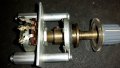
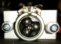
I found an old timey 84:1 !! friction driven ball bearing type concentric "gearbox" that was used once for very fine adjustment for an instrument pot.
in the process of mounting it to the quite sensitive encoder thereby enabling the slow & careful outputting of the encoder then check stepper motion. For torque, decided on the cheap way, to get relative readings using a very smooth skew wound DC motor coupled to its shaft & a variable power resistor to read dc o/p.
one thing that i do find puzzling.. When VSD's are used, especially with unshielded cable between the drive & the Induction motor, dv/dt filters have to be fitted to, 1. for higher power apps, stop the eventual damage to bearings & windings,
2. to assist in meeting EMI/EMC requirements.
yet Ive never seen dv/dt filters on the output of stepper drives (AFAIK). some bigger applications have the drive in the back of the stepper negating the need.
Also, Ive not seen heat sinks fitted to steppers, & some are real hot ~80C !! U can imagine what that does to the permanent magnets, bearings etc. A cost thingy?
Just for future reference you can use PSOC to drag and drop logic onto
a gui schematic sheet, and pins, then use wire tool to connect them, and
build the project without writing a single line of code. That of course will
only use 5% of the parts capability, but is a handy way of doing custom
small logic designs.
There are more sophisticated onchip resources, some where you
would only have to write a single line of code, Like "Counter_1_Start();",
and your in business.
Same goes for an OpAmp or Comparator or DAC...., drop onto schematic, wire it to
pins, and write one line of code, the "youropampname_Start();'
I use it for designs, many times of which I use it to create my own test bed
for signals, etc., and sometimes the no code simple logic designs I need.
I did tons of discrete logic designs in 70's, do not want to go back to using whale
oil lamps for light......New GUI tools like this with the hardware on chip so useful
and time saving, save the effort for the big ideas, not how many wires and parts
I can poke into solder less breadboard in a day...ugh.
And along with this accurate V and T generation compared to using discrete
approaches like 555 timer and its passive part cadre of components needed.
Just a thought next time you need to create a low end logic design.
one thing that i do find puzzling.. When VSD's are used, especially with unshielded cable between the drive & the Induction motor,
Also, Ive not seen heat sinks fitted to steppers, & some are real hot ~80C !! U can imagine what that does to the permanent magnets, bearings etc. A cost thingy?
Do you mean VFD's?
If so the 3ph inductor between the VFD and motor is to take out the harmonics that may be present, many do not bother to use them.
It does help on both motor and VFD.
When steppers overheat it is usually those that are using higher than the rated current, if this is within the rated plate current there should be no need for concern.
Max.
Do you mean VFD's?
If so the 3ph inductor between the VFD and motor is to take out the harmonics that may be present, many do not bother to use them.
It does help on both motor and VFD.
When steppers overheat it is usually those that are using higher than the rated current, if this is within the rated plate current there should be no need for concern.
Max.
Just for future reference you can use PSOC to drag and drop logic onto
a gui schematic sheet, and pins, then use wire tool to connect them, and
build the project without writing a single line of code. That of course will
only use 5% of the parts capability, but is a handy way of doing custom
small logic designs.
There are more sophisticated onchip resources, some where you
would only have to write a single line of code, Like "Counter_1_Start();",
and your in business.
Same goes for an OpAmp or Comparator or DAC...., drop onto schematic, wire it to
pins, and write one line of code, the "youropampname_Start();'
I use it for designs, many times of which I use it to create my own test bed
for signals, etc., and sometimes the no code simple logic designs I need.
I did tons of discrete logic designs in 70's, do not want to go back to using whale
oil lamps for light......New GUI tools like this with the hardware on chip so useful
and time saving, save the effort for the big ideas, not how many wires and parts
I can poke into solder less breadboard in a day...ugh.
And along with this accurate V and T generation compared to using discrete
approaches like 555 timer and its passive part cadre of components needed.
Just a thought next time you need to create a low end logic design.
...
Thankyou for your detailed efforts, explanation, Dana.
May i assume PSoC stands for programmable system on a chip?
Anyway wont be jumping ships midstream
...
U select underline from text control bar?
Looked at all 3 links.. wow peoples r busy!
Much appreciated. His link to Aluminite casting intriguing too.
Program 4 encoder tricky
Yes, do not jump ship, just store in back of mind. Also w/o investing in
a board there is a series of videos, ~ 15 min each, "PSOC 101:Lesson 1"
and first 5 will show you quite a lot.
psoc as brand too, or generic?
with real world logic in can set up any interface to other logic, analogue or machine by simply choosing the appropriate device.
ie, if logic o/p is 0-5v, & machine its driving wants 0-24V, can PSoC do that.
ie, does it have the ability to internally connect logic sections to different supply rails?
with real world logic in can set up any interface to other logic, analogue or machine by simply choosing the appropriate device.
ie, if logic o/p is 0-5v, & machine its driving wants 0-24V, can PSoC do that.
ie, does it have the ability to internally connect logic sections to different supply rails?
No, PSOC I/O cannot drive > than its Vdd range, max at 5V logic. However it
does have the capability to set pins to either a Vref or a table of set thresholds
for interfacing to other standard logic. You would use an external transistor to
accomplish 24 VDC control, as in traditional embedded design.....
The supply rails internal are fixed and not routable. The logic interface to the
fabric is routable, eg. wire a Shift Reg or Counter to a port, or other logic
inputs, or a control register.....
It does however have the ability to power off sections. And of course sleep, hibernate.... modes.
Turn OFF Unused Components The easiest way to reduce power in Active mode is to turn OFF unused PSoC Creator Components. Any Component that can be disabled in Active or Sleep mode includes a _Stop() function in its API. This function immediately halts all operation of the Component and sets it to its

 Facebook
 Google
 GitHub
 Linkedin