Stage Line 500W amp repair, help please

LesJones

Joined Jan 8, 2017
4,509
I have the version with the LCD display. It seems to work well. If you bought that version you would have to wait for it to arrive from China, assemble it and find a suitable enclosure. I think they are both the same except for the display technology.
You could just build the little test circuit to test the suspect device the way I described in post #217. If you so not have a 3K resistor you can use two 1.5 K resistors in series. The 15 K is a standard value and I used a 33K resistor in series with a 12 volt power supply to give a current of 2.5 mA. (The same current that passes through the transistor when it is in the amplifier.)

Les.
 

Thread Starter

Rookieme

Joined Jan 26, 2021
308
I have the version with the LCD display. It seems to work well. If you bought that version you would have to wait for it to arrive from China, assemble it and find a suitable enclosure. I think they are both the same except for the display technology.
You could just build the little test circuit to test the suspect device the way I described in post #217. If you so not have a 3K resistor you can use two 1.5 K resistors in series. The 15 K is a standard value and I used a 33K resistor in series with a 12 volt power supply to give a current of 2.5 mA. (The same current that passes through the transistor when it is in the amplifier.)

Les.
That sounds very interesting, could i use that setup to test the other transistors?
 

LesJones

Joined Jan 8, 2017
4,509
The test I performed was to confirm that the bias regulator worked as I expected and for you to do was to test the transistor as it it used in the amplifier. (Compare it with the schematic.)
I will explain the reasoning for suspecting Q29.
There are the voltage reading you took across the requested resistors together with the calculated current through them.
Voltage across resistors

R33=2.58 1K (2.6mA)
R41=2.53 1K (2,6mA)
R42=48.69 27K (1.8 mA)
R51=69.48 27K (2.6 mA)
R54=0.17 68R (2.5 mA)
R81=3.86 1K5 (2.6mA)
R82=3.93 1K5 (2,6 mA)
R86=1.38 270R (5.1 mA)
R57=1.23 15K (82 uA)
R65=0.13 3K (43 uA)
R88=0.00 100K (0)
R53=27.08 15K (1.8 mA)

From the voltage reading across R54 we know the current through it is 2.5 mA.
At the collector of Q29 this current splits two ways. 82 uA goes through R57 and the rest (About 2.4 mA) goes through Q29.
R65 is in parallel with the base emitter junction of Q29 and the voltage across it is only 0.13 volts so Q29 should not be conducting. (It should only start conducting when the base is about 0.6 volts positive of the emitter.
The only other thing I can think of that would cause these strange reading is some contamination on the etch side of the PCB causing leakage. The only thing I can think of that would do this is electrolyte leaked from an electrolytic capacitor. (It is worth checking for any contamination around the connections to Q29 before removing Q29.)

Les.
 

Thread Starter

Rookieme

Joined Jan 26, 2021
308
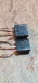
Ok, so i thought as a last attempt before the weekend, i swapped Q20 for Q7 wich i am sure i have changed for new, also changed Q36 for an origanal good one, still have audio but terrible quality so my guess is its possibly not Q29, however i will change it again when the new ones turn up, also still only half a sinewave transistor from Q7 is the o e with bent legs 20210826_202458.jpg20210826_192258.jpg
 
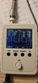
The scope looks like a DSO 150. I also have one along with a bunch of others.

Your going to have that flat side until you get the current stage fixed. Find out which BE junction isn't working. It does not have to be a transistor that's bad.

I routinely disable the bias regulator until I get a symmetric waveform with crossover distortion. The bias adjust gets disabled too. All good things. You can also adjust the bias to zero.

The bias regulator could be way off and you get instant thermal runaway.

It could be slightly off. If crossover distortion when cold.

It might not track because of poor thermal contact

The best way to adjust the bias regulator is with a distortion analyzer. Otherwise it's more complicated.
 

Thread Starter

Rookieme

Joined Jan 26, 2021
308
Is there anything else i can check in the mean time, tried to chase down the BE junctions but they all seem to be working, should the emitter of Q34 be --, as its showing the same voltage as Q26 emitter but both show positive voltage , also what controls the fan speed, it seems to be on fairly fast all the time
 

LesJones

Joined Jan 8, 2017
4,509
You could test Q29 out of circuit as I described in post #222. That is the exact way it is used in the amplifier. Until we get close to 4 volts between Q23 base and Q40 base the base emitter junctions of the emitter follower stages will not be forward biased.

Les.
 

Thread Starter

Rookieme

Joined Jan 26, 2021
308
You could test Q29 out of circuit as I described in post #222. That is the exact way it is used in the amplifier. Until we get close to 4 volts between Q23 base and Q40 base the base emitter junctions of the emitter follower stages will not be forward biased.

Les.
Might seem a silly request but could you post a photo of the setup you used, i will have to find a 12v power supply to,
Cheers

Pete
 

LesJones

Joined Jan 8, 2017
4,509
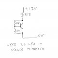
This is the circuit that I used. I just soldered the components together without any circuit board.

310821.jpgYou should get a reading of about 0.6 volts between base and emitter and about 3.6 volts between emitter and collector.

Les.
 

LesJones

Joined Jan 8, 2017
4,509
If it is a battery or power supply we will consider the negative terminal as the 0 volt reference. So the positive terminal is + 12 volts with respect to the 0 volts. We could just as easily considered the Positive terminal as 0 volts then the negative terminal would be - 12 volts with respect to the 0 volt reference.
Think about your amplifier. You have the 0 volt reference and two supply rails to the output stages. One at + 45 volts with respect to the 0 volt reference the other at - 45 volts with respect to the 0 volt reference.

Les.
 
Well, This:
@KeepItSimpleStupid

Here are the results of the readings you asked for,
No signal input

Q23B to Q28E = 0.633vdc
Q40B to Q36E = 0.918vdc
Q23B to Q40B = 1.566vdc

is still more important than the bias regulator. Q23B through Q28E

Walk your way, Negative probe on Q23B. Diode test mode.
Expected voltages in (), using the diode mode on your meter, no power.
Q23E = (~0.6)
*Q26E = (<0.9)
Q27E = (not fitted)
*Q28E =(-0.9) This is what you got on the other side.

In any case Q26E and Q28E should not be the same number. Use the other side for guidance.

Check R52, R62 and the emitter resistors.
You might have to take "*" out to check them.
 
Last edited:

Thread Starter

Rookieme

Joined Jan 26, 2021
308
On Q23 i get nothing with the negative probe on the base and red probe on emitter, however the corresponding transistor on the left chanel reads 1.223,

Q26 negative probe on base and red on emitter 1.044 but slowly climbs then falls,
Q28 negative probe on the base (emitter leg of Q26) and positive probe on emitter (top end of R64) i get 0.0103 but also get the beep as if its a dead short,
R52 reads 0.6726 kΩ,
R62 has been replaced previously and reads 10.15Ω,

All transisters were tested in circuit and on the diode test range with the power off,

Pete
 

Thread Starter

Rookieme

Joined Jan 26, 2021
308
@LesJones
Unfortunately i do not have the resistors or power supply to complete the task requested in post #235,
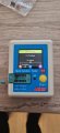
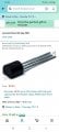
I litteraly have some spare bits i bought for this project, however i will be buying more kit as this project goes on, including a power supply, i did buy the transistor tester from Amazon, arrived today, with no instructions , but its fairly fool proof,

Pete
 
Top