Stage Line 500W amp repair, help please

LesJones

Joined Jan 8, 2017
4,509
I did not look at the picture of your meter. That reading is fine. If it had failed due to the output transistors failing short circuit it would probably read a high value.
You tend to learn things like this from experience. This is why I think you should have started in electronics on much simpler items.

Les.
 

Thread Starter

Rookieme

Joined Jan 26, 2021
308
I agree but i have a lot of time and effort invested in this thing now, and i do appreciate all the help and guidance from everyone, i also appreciate if it were in your hands you could probably diagnose and repair it in 1 day
 
let me ask a few questions: measured with signal unless otherwise noted.

1. The other channel is disabled (i.e. he fuses pulled)
2. Your still using an incandescent lamp?
3. The lamp isn't glowing bright?
3. The bias regulator is working?

4. I might not be on the correct channel, but the voltage between Q1b, Q22b or Q23, Q40
is not unresasonable. I think 3.6V ir so. Remember use other convienient components to
put your probes.

5. with a sine wave in, you have something that looks like a 1/2 a sine wave on Q1b and Q22base?
May not exact.

6. What does the speaker output look like?

7. With no signal what is the speaker DC voltage (voltage across speaker terminals)

8. What voltages do you have between LA and t5 and LB and T5 with no signal applied. Voltage should be small?

9a. Voltage between q1b and q18e?

9b. Voltage between q21b and q20e

With an incadesent lamp, waveforms will not be quite right,

This amp has a current limiter through R47 and the corresponding resistor. (I cant read p/n).
You have a voltage limiter with the diodes around q14 and q15.
Commonly called a VI limiter.
Components around D5 is part of the turn-on circuit.
c4 sets the low end frequency response.
C3 and the nearby R set the high frequency rolloff.
q7 is the temperatire fed back heatsink signal.
The components around q7 are what;s known as a Vbe multiplier.
Resistors around q8 for a T feedback network?
Note that there is a crowbar on the output (Triac).
Q17 and Q18 have to be matched for gain unless R35/R32 is not fittted.
Q19 and Q20 have to be matched for gain unless R35/R32 is not fittted.
No high volume with a load until that's done.
The amp is capable of bridging, so there's funky stuff at the front-end.

What I'm saying is that if things look "kinda OK", apply a signal, no load. Look at the output and also monitor the DC vale (scope is fine)

One of the final tests is to monitor the DC voltage across one of the emitter resistors vs time with no load, no signal.
 

Thread Starter

Rookieme

Joined Jan 26, 2021
308
Unfortunately my battery for my scope has died, because its cheap it runs off a 9v battery, possibly why the last results were all over, i will get new ones tomorrow and re do the readings in post #153 then try and work my way through the others requested
 
Since both channels are broken, we might put:
RE: Right channel repair in the top each post or whatever one is being trouble shot. We could also consider a new thread when the other channel is looked it with cross references to the threads. Conditions need to be spelled out too. I'm haveing a really tough.

@Rookieme: needs to look at more convenient places to probe There may be lots of placed related to base of Q*.

Some readings do depend on a symetrical power rail. The "bulb test" just has to show "activity" or signal.

The lamp protects against gross shorts.

In many amplifiers the bias current adjust sets the DC offset if the amp has one. +-750mV is the max range one should expect. Typically, it should be in the 10's of mV range or less. If there are protection relays, you have to look before it's activated.

The idle current is the other critical thing to look at. That is the voltage across one of the output emitter resistors.
If something is wrong, that current will increase very rapidly. You generally have time to monitor and turn things off.

It's unusual that the amplifier has separate fuses for each power rail. I did it for the amp I built too.
the amps had 4 supplies of 50VDC with 9600uF of filtering on each supply. That's a lot of capacitance to power up. What I did was placed a low value resistor in series with the AC line (47 ohms for 120 VAC). Then I loosely checked if each power rail is >2/3 of 50V. When that condition was true, the speakers were enabled and the inputs enabled with a FET optocoupler/
Now, if the amp didn't power up, in time, the 47 ohm resistor would smoke (It was a metal oxide resistor and they typically open). What I didn't do, was remove power if the amp did not power up in a certain amount of time.

I used a simple optocoupler and zener diodes for the 2/3 detection. I had to place a ZNR across the 9600 uF capacitors to remove the spike that would kill the optocoupler if they were not present.

The other cool think I did with the input FET optocoupler was it was placed in series with the audio input of the amplifier and I amplified the voltage across a timing capacitor, so the audio ramped up exponentially. When I fix it, I have a way of taking the board out and connect it to an extender and I have to short that 47 ohm resistor.

A current metered variac is an essential piece of test equipment for audio amplifiers.

I'm thinking:

That you have no serious problems and you can fully power up this channel with no load and a signal. Make sure the other one has the fuses removed.

I did see a DC protect light which in some cases mean the speaker is not connected. It doesn't look like there is a speaker relay in this amp. The protection mechanisms will probably introduce some unique challenges.

With the bias potentiometer not fitted suggests that MAYBE the output transistors are selected by Vbe.
 
The other channel (DC offset problem)

The emitter resistors are also known as fusible resistors. They totally open when they blow. Exact value meaningless/

What you can do is:

We really care about Q7 on out.

1) check the emitter resistors
2) Check any low value resistor. Your looking for grossly off values. 1k for 270 ohms.
3) Using the diode test on your meter, check the b-e voltage. Should be around 0.6V one way and OL the other.
If they read 0 and 0, that's a problem.

Those simple tests would probably fix 90-95% of power amp issues.

The Vbe multiplier/bias regulator is the next general issue. That needs to work. Disabling it, is always a good thing to do.

I kinda went through the initial power-up and some of the final tests. I left out temperature tests.
 

LesJones

Joined Jan 8, 2017
4,509
Rookieme, Are you using a X1 or X10 scope probe ? If you are using an X10 probe is the scale factor of 2 volts per division really 20 volts per division at the probe tip ? (Some scopes you can set them to take into account the probe scaling.)
When you get your test setup working and have confirmed that you see the positive half sine waves on the output do the following tests first. Measure the voltage at the collector of Q36 with respect to T9. Then check the wave form at the collector of Q36. IF YOU ARE SURE THAT YOUR SCOPE WILL NOT BE DAMAGED WITH - 45 VOLTS ON THE PROBE TIP you can leave it set to DC coupling. If not set it to AC coupling. (I had asked to to set it to AC coupling for the previous tests in case the fault put a high DC voltage on any of the points I asked you to test but I have noticed that you have the scope still set to DC coupling. (This has actually been better for the testing as we can see the DC level.) This the reasoning behind this test. I remember many months ago when you first came on the forum we got you to check all the supply rails an they were OK. I am wondering now if the -45 volts is not now present or not stiff enough to provide the negative part of the waveform. When there is no load on the output the drive from Q39 collector via the base emitter junctions may be enough to provide the negative part of the waveform. (Q39 is powered from the -55 volt rail.)

Les.
 
RE: Right channel troubleshooting

@LesJones Sometimes you forget the basics.
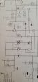
I'm having a really hard time reading the schematic on paper. I probably should rotate that page from portrait to landscape,
Now I know it's the right channel.

Because of the partial conduction (class AB) nearly everything has to work. Turning the amp into a class B amp makes it a little easier. Not sure how they got away with no bias adjustment?

PS (Aside): Still surrounded by rocks. The car had an alternator problem and it sure wasn;t like the old days. Initial failure was alternator light on/off for brief periods, no codes. Lots of voltage (12V). No way to check the battery charge (Hygrometer).

The next day the car jumped, but did not run quite right. No lights, no gauges, no wipers (it was raining), no power windows. Lights on: air bag, brake, ABS, check engine, alternator.

I did think BCM, alternator and battery. Earlier, I thought alternator, battery. Since I could not start the vehicle, I could not check current output. I usually test voltage, state of charge, current output and ripple. I was deprived of "state of charge".

I just ordered a new cell phone. A samsung galaxy S20 and I know that's going to create all sorts of problems. My old phone is a pre-historic Motorola Backflip. They asked me if it was a flip or smart phone, I said both. It has Google Market and not Google play and there seems no easy way to transfer contacts.

So, no replaceable battery. No headphone jack and a nano SIM. We call this progress. More stuff crammed into a small space.

What I'm going to try to do. I have a gizmo that can back-up a SIM card to a handheld device. Then the handheld device acts as a portable addressbook. I have a nano to regular SIM adapter. So, that's the plan. Writing the addresses doesn;t seem to be attractive. Not backing them up or having a written copy is even worse.

When I did have a hard drive crash caused, in part, by the laptop falling from a washing machine, I learned a few lessons:
a) Don;t connect to the router in the ceiling with the laptop on the washer
(put an accessible jack lower) I still have to plug both ends in.
b) A fall of that magnitude should result in a replacement drive.
c) The irrecoverable crash happened much later, moments before I was doing a "backup"
while a car was being fixed. The trip home, did the drive in and the backup didn;t complete.
d) I ordered a 5 TB RAID NAS system for home. A drive failed 2x, but replacing is just plug in a new drive and wait. It's obsolete. I've been told, that IF I follow a specific upgrade path, you can use the same drives.
e) You really need two RAID array systems, not one.
f) I really do need a UPS. I have an unconnected one. Not good either.

The hard drive crash happened because my ISP changed the billing method and the link speed didn't seem right. It wasn't. I should have replaced the drive when the laptop fell.
It lasted a good 6 months after the fall.

Back in the "old days", late 1970's there would be a "bad block count". When a system went down unexpectingly, the next boot would "clean the disk". It would fix all of the open bits of the file system and also make sure the disk was readable.

Things are harder and different now.
 

Thread Starter

Rookieme

Joined Jan 26, 2021
308
@LesJones
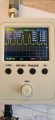
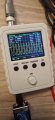
Hi, i tested the waveform from T9 to T34 and indeed again there is only the positave side,(see photo) also tseted Q36 collector voltage with respect to T9, it reads --64.49vdc, i havent checked the waveform on this point am my scope is only capable of 50v max, will it be ok on AC or using the DC with x10 on the probe ?

Also my sig gen has a pre amp, i am trying to keep that set in 1 position to keep testing consistant

This is with the resisters connected to T9 and T34, and right chanel volume set around the #2 position

Cheers

Pete
 

Attachments

LesJones

Joined Jan 8, 2017
4,509
If the scope is rated at 50 volts direct into the BNC socket it should be OK with the X10 probe wit -65 volts on the probe tip. (This will mean there is -6.5 volts into the BNC socket on the scope. To be on the safe side post the specifications for your scope for confirmation. I am curious why you are using T34 for looking at the output instead of T10. (For this test it does not matter as there is only a 0.22 ohm resistor and a 3 uH choke between them.) The signal level is not critical at the moment. (When I was in my teens I managed with the scope I had built which had no calibration on gain or sweep rate. And for injecting a signal by touching the grid pin of the valves to inject 50 hz mains pickup. There were very few transistors at that time.)

Les.
 

Thread Starter

Rookieme

Joined Jan 26, 2021
308
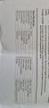
Its been so long since i took the amp apart i was relying on old photos fot the speaker output connection pionts, i will now use T9 and T10, will switch the scope probe to x10, and check from T9 to Q36 collector, here is the spec's of my scope, i will wait for your reply as weather to go ahead with the waveform test before i proceed,

Pete
 

Attachments

Thread Starter

Rookieme

Joined Jan 26, 2021
308
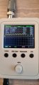
Here is the results of the waveform from T9 to Q36 collector, had to increase the V/DIV TO 5mv to get a reading resisters now connected to T9 and T10

The scope is currently on AC

Pete
 

Attachments

Last edited:

LesJones

Joined Jan 8, 2017
4,509
That seems to rule out my theory from this morning. So back to following the signal from Q40 base through the emitter follower stages to the output.

Les.
 

Thread Starter

Rookieme

Joined Jan 26, 2021
308
Just a theoty but can i just follow the waveform from Q40 emitter to Q37 base, Q34 base to Q36 base then Q36 emitter looking for a change,

Pete
 

LesJones

Joined Jan 8, 2017
4,509
As soon as you get to just seeing the positive half of the sine wave you don't need to go any further. The point where it changes from a full sine wave to just positive peaks will be close to the fault. If is is just the positive part of the sine wave at Q40 base we will need to start moving towards the input.
Les.
 

Thread Starter

Rookieme

Joined Jan 26, 2021
308
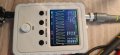
What does it mean when the waveform looks like a full signal but will only appier in the bottom half of the scope, is that just a negative signal ?

Juat i have Vmin but no Vmax
That was from Q40 E
 

Attachments

LesJones

Joined Jan 8, 2017
4,509
Re post #177 The signal has a DC offset of -3.73 volts. You do have a Vmax of -0.32 volts. If you switch to AC coupling the DC offset will be removed an the display will be centered on the horizontal center of the display.
Re post #178 I did say start from the base of Q40 So it looks like the signal has passed through Q40 OK.

Les.
 
Top