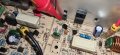
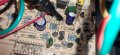
My days, dont know why i didnt realise this earlier, i have been trying to probe the transistors directly, obviously i can move down the circuit to a more convenient place that is directly connected for ease of access doh, promis am not this stupin in real life hahah
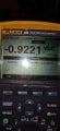
With the negative sign that reading is OK.
Back to following the signal through the amplifier. With the power off first measure the resistance of R73. Even though you have good DMM it probably won't read accurately with such a low value resistor. If it has failed it will read much more than 0.22 ohms.
If it is faulty don't bother with the following tests.
Now set up the amplifier as before with the same level signal input and with the dummy load resistor connected to the output.
Connect the ground wire from your scope probe to T9. Connect the probe tip to T10. I expect you to have the same positive half of a sine wave as before. Now probe the probe tip to Q36 base and get a picture of the waveform. Then move the probe tip to Q36 emitter and get a picture of the waveform. Post the results.
With the negative sign that reading is OK.
Back to following the signal through the amplifier. With the power off first measure the resistance of R73. Even though you have good DMM it probably won't read accurately with such a low value resistor. If it has failed it will read much more than 0.22 ohms.
If it is faulty don't bother with the following tests.
Now set up the amplifier as before with the same level signal input and with the dummy load resistor connected to the output.
Connect the ground wire from your scope probe to T9. Connect the probe tip to T10. I expect you to have the same positive half of a sine wave as before. Now probe the probe tip to Q36 base and get a picture of the waveform. Then move the probe tip to Q36 emitter and get a picture of the waveform. Post the results.
With the negative sign that reading is OK.
Back to following the signal through the amplifier. With the power off first measure the resistance of R73. Even though you have good DMM it probably won't read accurately with such a low value resistor. If it has failed it will read much more than 0.22 ohms.
If it is faulty don't bother with the following tests.
Now set up the amplifier as before with the same level signal input and with the dummy load resistor connected to the output.
Connect the ground wire from your scope probe to T9. Connect the probe tip to T10. I expect you to have the same positive half of a sine wave as before. Now probe the probe tip to Q36 base and get a picture of the waveform. Then move the probe tip to Q36 emitter and get a picture of the waveform. Post the results.
0.22 ohms is too close to the contact resistance. You might not even get zero when you short your probe tips together.
It's basically too low to measure without a zeroing technique or a 4-terminal measurement. there are such thingb sas a 4-terminal resistor. That's what a shunt is. The high current path is a longer path. The precision path is the small screws. e.g. 100mV for 100Amps.
I took a close peek at the amplifier and it's going to be really tough to troubleshoot. You have overvoltage protection, VI limiting, DC protection, clipping indicator, some sort of soft turn-on. A crowbar on the speaker terminals.
So, your using a ____ W incandescent lamp and it's not glowing right? If it is glowing what channel is it from and what are the symptoms? You said a) dead and b) partially working.
The lamp method generally protects against blowing parts because of shorts. It's not a great operate method.
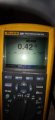
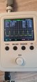
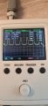
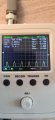
Here are the results,
Black probe on T9, resisters connected and sig gen set as close as i can remember first image T9 to T10,
Then T9 to Q36 base, then T9 to Q36 emitter,
I notice now as i am increasing the volume F2 resister fuse is getting hot and the LED gets brighther the higher i turn the volume
In post #111 the waveform at the Q34 emitter was totaly different to the waveform at Q36 base in post #153 (These are both the same point.) Are you sure that in post #111 that the load resistor was connected correctly because in post #109 it looks like the sleeve on one of the resistors goes inside the screw connector ? Also did you test resistor R73 ?
In post #111 the waveform at the Q34 emitter was totaly different to the waveform at Q36 base in post #153 (These are both the same point.) Are you sure that in post #111 that the load resistor was connected correctly because in post #109 it looks like the sleeve on one of the resistors goes inside the screw connector ? Also did you test resistor R73 ?
I tried the load resistors in a speakon connector but could not get a reading on the scope so connected the resistors to the T9 and T34 and skipped the rear jack, wiring,
In post #111 the waveform at the Q34 emitter was totaly different to the waveform at Q36 base in post #153 (These are both the same point.) Are you sure that in post #111 that the load resistor was connected correctly because in post #109 it looks like the sleeve on one of the resistors goes inside the screw connector ? Also did you test resistor R73 ?
In post #111 the waveform at the Q34 emitter was totaly different to the waveform at Q36 base in post #153 (These are both the same point.) Are you sure that in post #111 that the load resistor was connected correctly because in post #109 it looks like the sleeve on one of the resistors goes inside the screw connector ? Also did you test resistor R73 ?
I am convinced that in post #111 the load resistor was not connected so we need to start close to the beginning of the power amplifier section. I am going to give you a longer list of tests as it takes such a long time to see the results of the tests. I can understand that it take you much longer than the few seconds it takes wen working hands on as you have to photograph the traces, transfer them from your camera to you computer, crop them then add them to the post. With the same signal level and the load resistor connected get the traces at the following points.
Q40 base, Q37 base, Q34 base, Q35 base, Q36 emitter, T10. All of these test with the scope ground wire connected to T9
Also measure the voltage between T9 and Q36 collector with your meter.
I assume that R73 measured a low value. (You did not give the reading. You just said it was the same as others in similar positions.)
When measuring low value resistors first touch you meter probes together and note the reading. This will be the resistance of your test leads. You can then subtract this amount from the reading you get when testing the resistor.

 Facebook
 Google
 GitHub
 Linkedin