Stage Line 500W amp repair, help please

LesJones

Joined Jan 8, 2017
4,509
Hi kiss, I agree it is much more stressful doing remote faultfinding with someone with almost no electronics knowledge at the other end. Tests that take a few seconds when you are doing them take days. (Like the last test on the 3 stage emitter follower and we have still not had the result of the requested voltage test on the bias regulator voltage.) I will continue to help the TS of you prefer. I also have the advantage of being in the same time zone as the TS.

Les.
 

MrChips

Joined Oct 2, 2009
34,953
Hi kiss, I agree it is much more stressful doing remote faultfinding with someone with almost no electronics knowledge at the other end. Tests that take a few seconds when you are doing them take days. (Like the last test on the 3 stage emitter follower and we have still not had the result of the requested voltage test on the bias regulator voltage.) I will continue to help the TS of you prefer. I also have the advantage of being in the same time zone as the TS.

Les.
One time on AAC we were trying to trouble shoot an oscilloscope remotely online. It turned out the member was 20 minutes drive away from me. We got together and was able to find the fault very quickly.

If you are so inclined you can try sending PM and find out how far away the TS is located.
 

LesJones

Joined Jan 8, 2017
4,509
That voltage is far too high. Can you double check that you were on the collector of Q24. (NOT the emitter.)
Measure the voltage between the collector and emitter of Q29.
Measure the voltage on Q24 collector with respect to point T9. (Black probe on your meter to T9. Red probe to Q24 collector.)
Measure the voltage on Q29 emitter with respect to point T9. (Black probe on your meter to T9. Red probe to Q29 emitter.)

Edit I have just read your post #128. If you look at the schematic you will realise that those two points are are same two points as
Q24 collector and Q29 emitter. So one of your readings must be wrong. (Unless there is an open circuit track on the board which is VERY unlikely.)
Teesside is about 143 miles from my location so we are too far apart.

Les.
 
Last edited:
Your looking for a number, probably (3 to 4 * 0.7V) *2 ) 1.4, 2.8, 3.2, 4.8 V. Again, I'm not looking at the schematic. Zero is an OK number to have at this stage. It depends on the number of B-E junctions it has to regulate. The minimum is 2 in multiples of 2. The 0.7 can be 0.6 to 0.7V.

I think there are other more easily accessible components that are attached to the same place.

yea, I need to print the schematic.

==

You can generally find info with "2n3904 datasheet" or whatever. Generally, you;ll get some confusing mess.

If it's an orderable part, you can goto www.digikey.com or www.mouser.com and get the datasheet there.
 
Last edited:

Thread Starter

Rookieme

Joined Jan 26, 2021
308
Your looking for a number, probably (3 to 4 * 0.7V) *2 ) 1.4, 2.8, 3.2, 4.8 V. Again, I'm not looking at the schematic. Zero is an OK number to have at this stage. It depends on the number of B-E junctions it has to regulate. The minimum is 2 in multiples of 2. The 0.7 can be 0.6 to 0.7V.

I think there are other more easily accessible components that are attached to the same place.

yea, I need to print the schematic.

==

You can generally find info with "2n3904 datasheet" or whatever. Generally, you;ll get some confusing mess.

If it's an orderable part, you can goto www.digikey.com or www.mouser.com and get the datasheet there.
Then the number is 0.1753, if the pinout i have is correct
 
TS in forum speak is Thread Starter. It used to be the OP or Original Poster.

When the bias regulator is bad, it usually doesn't affect the symmetry, but you have some weird stuff going on there.

What I did when I fixed the impossible amp, was I troubleshot the regulator with a 9V battery and a resistor and the amp not plugged in. You don't blow things up that way. Totally disabling the regulator is another technique.

I need to do some stuff ad I also need to print a schematic.
 

Thread Starter

Rookieme

Joined Jan 26, 2021
308
That voltage is far too high. Can you double check that you were on the collector of Q24. (NOT the emitter.)
Measure the voltage between the collector and emitter of Q29.
Measure the voltage on Q24 collector with respect to point T9. (Black probe on your meter to T9. Red probe to Q24 collector.)
Measure the voltage on Q29 emitter with respect to point T9. (Black probe on your meter to T9. Red probe to Q29 emitter.)

Edit I have just read your post #128. If you look at the schematic you will realise that those two points are are same two points as
Q24 collector and Q29 emitter. So one of your readings must be wrong. (Unless there is an open circuit track on the board which is VERY unlikely.)
Teesside is about 143 miles from my location so we are too far apart.

Les.
That voltage is far too high. Can you double check that you were on the collector of Q24. (NOT the emitter.)
Measure the voltage between the collector and emitter of Q29.
Measure the voltage on Q24 collector with respect to point T9. (Black probe on your meter to T9. Red probe to Q24 collector.)
Measure the voltage on Q29 emitter with respect to point T9. (Black probe on your meter to T9. Red probe to Q29 emitter.)

Edit I have just read your post #128. If you look at the schematic you will realise that those two points are are same two points as
Q24 collector and Q29 emitter. So one of your readings must be wrong. (Unless there is an open circuit track on the board which is VERY unlikely.)
Teesside is about 143 miles from my location so we are too far apart.

Les.
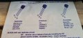
Ok after some pinout searching on digikey this is what i get,
Q24C to Q29E=1.533vdc
Q29C to Q29E =1.372vdc
Q24C T9= 0.647vdc
Q29E to T9 = 0.66vdc
 

Thread Starter

Rookieme

Joined Jan 26, 2021
308
LInk to datasheet for MPSA92

Link to datasheet for BC549

You don't have to go directly on the point given you can use the schematic that may be easier to reach or identify.
TS stands for thread starter. (Sometimes OP may be used for original poster.
Thank you for that, i now have it correct and the readings are from the correct place, am i right in thinking these are the 2 main configurations used in this amp, NPN and PNP also ?
 
Top