Stage Line 500W amp repair, help please

Thread Starter

Rookieme

Joined Jan 26, 2021
308
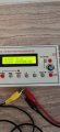
I honistly think i am making this more difficult than it actualy is, i am pretty sure the preamp is working ok on both chanels, i am planning on re printing the schematic and testing each componant on 1 chanel and noteing the result, then compairing it to the schematic, then do the same for the other chanel, the problem i am going to have is that i have changed componants on both sides already so the sound would hopefully be the same, the little scope and sig gen seem to work ok ish, hopefully these will help me pin point a fault, although the leads dont seem to calabrate well, probably cheap leads
 

LesJones

Joined Jan 8, 2017
4,509
I suggest starting on the right hand channel. With power on but no signal injected measure the DC voltage across the following resistors. (I.E one meter probe on each end of the resistor.) R55, R56, E84, R85, R81, R82. I suggest that you record these values in a spreadsheet program or text file. Also add a note to each entry with the conditions that the measurement was taken. (In this case "no signal injected. You could also note right or left channel.)
now inject about the same level signal as you did in post #82. (You did not say where you injected the signal.) Verify that the output signal is the same as it was in post #82. Now connect your scope probe to the junction of R69 and R77 and post a picture of the display. This is the input to the power amplifier section and we know from the value of R69 and R67 that the ratio of the AC voltage at the output should be -6 times the voltage at the junction of R69 and R77. (The - sign indicates that the signal is inverted between the input and output. Which time zone are you in so I can pick the best times to post. My local time now is 18:00 (UK summertime.).

Les.
 

Thread Starter

Rookieme

Joined Jan 26, 2021
308
I suggest starting on the right hand channel. With power on but no signal injected measure the DC voltage across the following resistors. (I.E one meter probe on each end of the resistor.) R55, R56, E84, R85, R81, R82. I suggest that you record these values in a spreadsheet program or text file. Also add a note to each entry with the conditions that the measurement was taken. (In this case "no signal injected. You could also note right or left channel.)
now inject about the same level signal as you did in post #82. (You did not say where you injected the signal.) Verify that the output signal is the same as it was in post #82. Now connect your scope probe to the junction of R69 and R77 and post a picture of the display. This is the input to the power amplifier section and we know from the value of R69 and R67 that the ratio of the AC voltage at the output should be -6 times the voltage at the junction of R69 and R77. (The - sign indicates that the signal is inverted between the input and output. Which time zone are you in so I can pick the best times to post. My local time now is 18:00 (UK summertime.).

Les.
Hi, i am in the UK,
I injected the signal into the input at the rear red and white push in type connectors, i will take the measurements you asked for and post my findings soon,

Thanks i advance
 

Thread Starter

Rookieme

Joined Jan 26, 2021
308
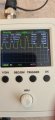
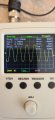
Ok this is what i get with the amp on, no signal and volume to zero,
R55=0.422vdc
R56=0.416vdc
R84=5.907vdc
R85=5.798vdc
R81=3.821vdc
R82=3.961vdc

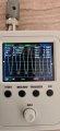
Photo is with volume turned to 2,

Do i need to conne t the negative lead of the probe to anywhere ?
 

Attachments

LesJones

Joined Jan 8, 2017
4,509
You do need to connect the negative lead from the scope probe to the zero volt rail. T9 (Marked 0VP) is probably a convenient place to connect it. You also need to connect it to this point when looking at the output signal. You also need to connect the negative wire from the signal generator to this point. The outside metal of one of the input phono sockets is probably more convenient for this. Can you repeat the test with the black lead from the signal generator and the scope connected also repeat the test on the amplifier output with the black leads connected. I want to compare the signal levels between the power amplifier input and output to see is the ratio is close to the calculated value of 1:6.

Les
 

Thread Starter

Rookieme

Joined Jan 26, 2021
308
Ah dam it i did connect the scope black to T9 then removed it, i will redo the test tomorrow and poat the photos
 

LesJones

Joined Jan 8, 2017
4,509
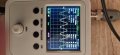
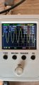
Something has changed since yesterday as yesterday you only had the positive part of the sine wave at the output. today you have a full sine wave. The amplifier seems to almost working correctly. It's gain only seems to be about 5.2 when I calculated it should be 6.
Try connecting a load to the output. Try a 10 ohm 5 watt resistor and see if the output remains about the same as it is without a load.

Les.
 

Thread Starter

Rookieme

Joined Jan 26, 2021
308
Something has changed since yesterday as yesterday you only had the positive part of the sine wave at the output. today you have a full sine wave. The amplifier seems to almost working correctly. It's gain only seems to be about 5.2 when I calculated it should be 6.
Try connecting a load to the output. Try a 10 ohm 5 watt resistor and see if the output remains about the same as it is without a load.

Les.
Yes yesterday i did have a small speaker connected, but i have no idea what ohm rating it is
 

Thread Starter

Rookieme

Joined Jan 26, 2021
308
If i connect a speaker to the output i do get sound and gain with the volume knob, but its nowhere near what it used to be and its badly distorted at all volume levels
 

LesJones

Joined Jan 8, 2017
4,509
With the load resistor connected to the output first confirm that you only see the positive half of the sine wave.
If so then post pictures of the wave form at the base of Q40, the emitter of Q40, the emitter of Q37 and the emitter of Q34.

Les.
 

Thread Starter

Rookieme

Joined Jan 26, 2021
308
Also not sure if you and everyone else is aware, when i first started this project way back in 2017, i made these fuse replacements with fuseable resistors , would it be better to replace these with some fast blow fuses to ensure good connectivity as there a bit bulky, i was advised to make these to show what fuse the fault was on , they have 2 LED'S attached in opposite polarity
 

Attachments

Thread Starter

Rookieme

Joined Jan 26, 2021
308
With the load resistor connected to the output first confirm that you only see the positive half of the sine wave.
If so then post pictures of the wave form at the base of Q40, the emitter of Q40, the emitter of Q37 and the emitter of Q34.

Les.
Will come back when i have this resistor ,

Cheers

Pete
 

LesJones

Joined Jan 8, 2017
4,509
Leave it as it is for the moment. We will worry about that when we get to the stage of testing it near it's rated output. With a 10 ohm load and the output at 5 volts RMS the output power will only be 2.5 watts.
Any resistor between about 5 and 30 ohms will do for now.
Edit. By the way set the scope to AC coupling for these tests.
Les.
 
Last edited:

Thread Starter

Rookieme

Joined Jan 26, 2021
308
Leave it as it is for the moment. We will worry about that when we get to the stage of testing it near it's rated output. With a 10 ohm load and the output at 5 volts RMS the output power will only be 2.5 watts.
Any resistor between about 5 and 30 ohms will do for now.
Edit. By the way set the scope to AC coupling for these tests.
Les.
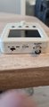
AC coupling ? , i dont think this scope does that, it has AC, DC and GND
 

Attachments

LesJones

Joined Jan 8, 2017
4,509
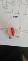
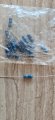
There is nothing in the picture to give sense of scale so I can only make a guess at there rating. I I assume they are 0.5 watt rating then use 4 connected as two pairs connected in parallel connected in series. (This will make 10 ohms with 2 watts rating.)
They will probably get hot particularly when we fix the fault.

Les.
 

Thread Starter

Rookieme

Joined Jan 26, 2021
308
There is nothing in the picture to give sense of scale so I can only make a guess at there rating. I I assume they are 0.5 watt rating then use 4 connected as two pairs connected in parallel connected in series. (This will make 10 ohms with 2 watts rating.)
They will probably get hot particularly when we fix the fault.

Les.
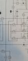
Just looked on the left chanel schematic, those resistore were to replace R30
 

Attachments

Top