Stabilisation issue in the negative range of my LM324

Thread Starter

ryanafleming

Joined Sep 25, 2017
2
Hi guys,

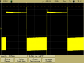
I have been working with a TI quad LM324 op amp and have been running into an issue on my boards. Simulations for the below circuit on LT Spice show me as expected that my 1khz pulse inverts to 1/5th of the amplitude of my input signal. Though when I do this practically below as seen on my scope, I get ringing at 910kHz with an amplitude of 210mV and can't work out whats going on?

Initial bode plot results show that I have a PM of roughly 47, but I'm a bit of a noob at doing them and pretty sure I did it wrong!

Cheers,
Ryan.
upload_2017-9-26_17-6-21.png
 

Attachments

Alec_t

Joined Sep 17, 2013
14,314
Is your circuit built on a breadboard?
Are the dual supplies decoupled by appropriate capacitors at the opamp supply pins?
Do the circuit and scope have a single-point ground?
 

OBW0549

Joined Mar 2, 2015
3,566
Though when I do this practically below as seen on my scope, I get ringing at 910kHz with an amplitude of 210mV and can't work out whats going on?
It sounds to me like your op amp is oscillating. They like to do that, unless you strongly discourage them. Some suggestions:

  1. Make sure you have the LM324's power connections properly decoupled: a 0.1 μF capacitor from the Vdd pin to ground, as close to the Vdd pin and the op amp's (+) input as possible, and another 0.1 μF capacitor from the Vss pin to the same ground point;
  2. Connect a resistor, ≈ 2 kΩ to 10 kΩ, from the op amp's output to either Vdd or Vss (Vss is probably better), to "pre-load" the LM324's output stage so that either the internal current-sourcing transistor(s) or the current-sinking transistor(s) is on all the time and the LM324 doesn't have to flip back and forth between sourcing and sinking; and
  3. Connect a small capacitor, ≈ 50 pF to 200 pF, across R1 in your diagram, in case the oscillation is being caused by loop instability due to parasitic capacitance on the op amp inputs (breadboards can do this).

Maybe one of these will do the trick...

EDIT: If you want some theory, this app note may help.
 

AnalogKid

Joined Aug 1, 2013
11,044
Without an actual image of the actual ringing, it's all guesswork. But ... check the scope probe compensation, and make sure the Ground clip lead is as short as possible. This probably is not the main problem, but it is on the list of standard stuff to check.

ak
 

OBW0549

Joined Mar 2, 2015
3,566
...and make sure the Ground clip lead is as short as possible.
Amazing the number of people who get bit by that, forgetting that a scope probe's ground lead has inductance and that inductance forms a series resonant circuit with the probe's capacitance. Feed it a signal with fast rise & fall times, and voilà: horrible ringing on the scope trace, even though their signal is actually quite clean.
 

AnalogKid

Joined Aug 1, 2013
11,044
Had a young'n struggling with ringing on a flyback switcher transition, who didn't think it mattered. While he was glaring at the scope, I sat a bottle of water next to the prototype where the scope was attached. The ringing changed; he changed.

ak
 

OBW0549

Joined Mar 2, 2015
3,566
Had a young'n struggling with ringing on a flyback switcher transition, who didn't think it mattered. While he was glaring at the scope, I sat a bottle of water next to the prototype where the scope was attached. The ringing changed; he changed.
Ah, young'ns. I went to work one day, early as usual (normally the first one there), and walking through the lab on the way to my office I saw a couple of other engineers there (software guys), hunched over a scope with worried looks on their faces. Shortly after I got to my desk one of them came over and asked if I could give them some help.

He explained: they were probing around the backplane on their new system looking at timing signals, strobes, data lines, address lines and so forth, and ALL of the signals they'd looked at looked like crap on the scope, with absolutely hideous ringing. They'd been there all night long, since noon the day before, trying to figure out why their signals looked so horrible and were at a loss.

Hmmm.

So I asked him, "Does it work? Is your system executing its test program correctly?" And he answered, "Yeah, that's the crazy thing: it seems to be working perfectly! And we can't understand how it could possibly function at all with all of the signals that screwed up!"

Hmmm.

So we go back to the lab and I said, "OK, show me the problem."

And he probed around, one signal after another, and sure enough-- they looked horrible. Undershoot, overshoot, ringing all over the place. "Yup. That looks bad, for sure."

(Of course, the first thing I noticed when I walked up to their setup was the scope probe ground lead: they had extended it, for convenience, with a 2-meter clip lead so they could probe around more easily. Just as I figured.)

As he was showing me the signals and talking, I began slowly twisting the huge loop of ground wire, collapsing the loop and forming it into a tight, twisted pair. And as we watched the scope, the ringing got smaller and smaller until the loop was completely closed, whereupon it disappeared completely. Nice, clean signals.

The looks on these guys' faces was priceless. "What the heck did you DO??????"

So I explained about inductance, capacitance, resonance and the importance of short ground leads, and then left them to bemoan the fact that they'd just spent the last 18 hours or so chasing a non-problem.

Still brings a smile to my face, 25 years on.
 

Thread Starter

ryanafleming

Joined Sep 25, 2017
2
The board more or less got passed on to me. We were using quad opamps and had a spare, so I think it was a "why not" moment.

A few notes based on everyones questions
- The board is power directly from a dual bench top supply where the ground has been earthed.
- The Opamp has been decoupled by 2x100nF capacitors that have been placed closed so its Vdd to ground and Vss to ground.
- The scope's ground was also earthed (not battery isolated scope) so I tested using its ground pin and without, same results.
- My leads are all roughly 30cm-40cm each. Standard banana leads and aligator
- The circuit is on a custom PCB made from PCBWay (as we all do) surrounded by a ground plane below it and around it

Attached is the model I am using that I downloaded from these forums a while back (forgot the link sorry). And the schematic of what I had done.

I'll have a go with some pico caps in parallel on the feedback and let you know the results!
 

Attachments

Top