Squaring Up Square Waves!

Thread Starter

RanHam335

Joined Dec 4, 2008
11
Hi everyone, this is my first post on this forum and I don't think it will be my last.

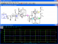
I want to play a biphase stream of square waves from my ipod to a circuit board to be decoded. The only problem is the board can only decode it if its a clean, squared-up biphase signal in the range of 0-10V. And as all of you might guess an ipod doesn't output that. So I need to use two op amps to achieve this. Now I hardly know anything about circuits can anyone help me lay out one for this project.

Thanks
 

SgtWookie

Joined Jul 17, 2007
22,230
What does your Ipod output?

I have doubts about either of the previous posters' replies for chances of a happy ending.
 

Wendy

Joined Mar 24, 2008
23,415
Sounds like the TRS80 cassette input. Hated that sucker. Wookies right, the 555 will need an amp in front. What frequency is the square wave?
 

SgtWookie

Joined Jul 17, 2007
22,230
Here's an approach for you. See the attached.

R1 gives a static 32 Ohm load to the IPod output for impedance matching. 33 Ohms is a standard value you could use.

C1 allows the effects of an AC signal to pass, but blocks DC levels.
R2 and R3 cause the input signal to float at roughly Vcc/2, or 5v.

R4/R5 give opamp U1 a gain of about 19.2. This may be excessive; I don't know what your Ipod output signal level is. R4 can be reduced to reduce the gain. If R4=0, gain is 1; gain increases by 1 per every 5k
Basically, gain = (5k+R4) / R4. You might want to replace R4 with a 50k pot wired as a rheostat.

R5 should be initially adjusted so that with no signal in, there is 0v difference between points (A) and (B).

R6 adjusts the trigger level for both comparators.
R7 and R8 are pull-up resistors for the comparator's open-collector outputs. These resistors should be roughly 330 Ohms per volt; since Vcc=10, they're 3.3k.
R9 is for hysteresis. This helps to prevent false triggers, and also helps ensure that the comparators switch at about the same time.

I've used comparators instead of opamps because that's what should be used in open-loop situations. A simple inexpensive comparator provides nearly rail-to-rail outputs, and minimal current usage. An opamp in open-loop mode would have it's outputs saturated, causing heating and wasted power. Besides, rail-to-rail opamps are more expensive than common comparators.
 

Attachments

Last edited:

Thread Starter

RanHam335

Joined Dec 4, 2008
11
I dug up info about the tape player from the manual. The tape player itself is what originally boosted the signal. Attached is info about the tape player and and the schematic. I cant really understand anything. Hope this helps.

Thanks alot everyone for your suggestions
 

Attachments

Wendy

Joined Mar 24, 2008
23,415
Is this to encode digital data by chance? It really does resemble the old days of using a cassette drive to hold computer programs.
 

SgtWookie

Joined Jul 17, 2007
22,230
Looks to me like it could've been to decode signals to drive music equipment, perhaps pseudo-MIDI signals, but the output connector would have hooked up to something to process the other inputs together. A standard MIDI connector is a 5-pin DIN plug/jack, and handles data serially. The data rate provided by the cassette circuit would have been quite slow.

And Bill, the TRS-80 cassette tape interface was actually quite good for what it was. It was the magnetic media of the day that was it's weak point. And yes, it was terribly slow, but infinitely faster than re-typing an entire program every time you wanted to do something.
 

Thread Starter

RanHam335

Joined Dec 4, 2008
11
Wookie your right it was used to drive solenoids to play pianos. But it is completely different then midi, this was created in the 70s Im using it to control something else.
 

Wendy

Joined Mar 24, 2008
23,415
Looks to me like it could've been to decode signals to drive music equipment, perhaps pseudo-MIDI signals, but the output connector would have hooked up to something to process the other inputs together. A standard MIDI connector is a 5-pin DIN plug/jack, and handles data serially. The data rate provided by the cassette circuit would have been quite slow.

And Bill, the TRS-80 cassette tape interface was actually quite good for what it was. It was the magnetic media of the day that was it's weak point. And yes, it was terribly slow, but infinitely faster than re-typing an entire program every time you wanted to do something.
Trust me, it sucked, quite badly. I used to save days of coding 3 times each on several cassettes, and still lost work because it wouldn't load. The Commodore PET didn't have that problem, because they used FSK. The TRS80 tried to encode digital pulses on the cassette, not sound, though an analog cassette port. I am extremely familar with it, having owned several generations of Trash80's. The reason I brought it up is it resembled what the poster did. A minor improvement was created on regenerating these pulses using a 74C14, the classic hex schmitt trigger, but I still lost work.

I am somewhat of a vintage computer expert, it's where I cut my teeth writing machine code and assembly (there is a difference, though minor). TRS80 Model 1, Tiny BASIC and advanced, TRS80 III, PET, Sinclair Z80, C64, C128, and more.

Wookie your right it was used to drive solenoids to play pianos. But it is completely different then midi, this was created in the 70s Im using it to control something else.
So is this frequency shift encoding, or digital pulses?
 

Thread Starter

RanHam335

Joined Dec 4, 2008
11
I think its frequency shift but I could be wrong. I havent been able to play around with it because i had no way to play the data, thats why i need to build this circuit. I tried to attach a sample of the data but the file was too big
 

SgtWookie

Joined Jul 17, 2007
22,230
Try zipping it up and attaching it.

Bill, I still have my Model I. And my Model 4P.
I still have some books that Dennis Bathory Kits and Harve Pennington wrote about the Model I in the late 70's/early 80's. I installed the lowercase mod pseudo-dead-bug style, with a selector switch on the back of the case, a lowercase driver and a KB debounce routine using EDTASM. I remember when having 16k of RAM was a big deal.
 

Wendy

Joined Mar 24, 2008
23,415
Yeah, I have mine too. I gave up on the series when a floppy on my Model III went out, and they never did fix the problem. I think they forgot to put the terminating resistors on the top drive. I regularly ran out of memory space for the 16K mod, but I did love the BASIC. Found more than one bug concerning how it handled the Z80 stack though. Once I went to Commodore (and Never Ever lost programming work again) I never looked back. My TRS80 Model I with tiny BASIC was how I established my first credit, took a $200 loan from bank in 1978 to buy one, about 6 months after I got my first real job. I have ALL my books, a rather extensive library that. Want them?

Back to the OP post.

I'm wondering if a narrow hysterisis Schmitt Trigger after a low pass filter might clean up his signal better. I'm thinking noise removal followed by data recovery. What do you think?
 

SgtWookie

Joined Jul 17, 2007
22,230
Well, the circuit I posted is basically a narrow hysterisis Schmitt trigger. And even with a pretty fast opamp, running much gain at all will certainly lop off the higher frequencies.

But since the input will be more or less a sinewave, a low pass filter might lose some information.

It would help a great deal to have a sample of the signal he's dealing with.
 

Thread Starter

RanHam335

Joined Dec 4, 2008
11
I attached a 30 second sample. I have documentation on how the sample is encoded, i'll have to dig it up. Eventually Ill create a program that will recreate this signal so I can program my own sequences.
 

Attachments

Wendy

Joined Mar 24, 2008
23,415
Does anyone have a utility to graph out a wave file?

The sound strongly resembles the TRS80 signal, not exact, but close. I was thinking of the low pass filter to kill noise. You shouldn't loose any signals below the roll off, so you make the roll off a little higher than usual.
 
Last edited:

DickCappels

Joined Aug 21, 2008
10,153
From your zipped file, you are simulating this with an LM741. This antique is pretty slow in terms of gain-bandwidth product and slew rate. Your circuit would probably work if you build it in the real world and use an suitable comparator instead of an op amp.
 
Top