Facebook
 Google
 GitHub
 Linkedin
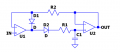
I have a square waveform with Positive Voltage of 17.5V and Negative Voltage of 3V with a Switching frequency of 40kHz and duty cycle of 0.5
This waveform is intended to drive a MOSFET.
But before connecting to MOSFETs in production line, I want to check the driver board for Positive voltage, Negative voltage, Switching Frequency.
I am thinking to use Peak detector to detect Positive and negative peaks. And Zero Crossing detector for Switching Frequency.
Is there any other methodology to detect same before connecting MOSFETs ?