And please post either a scope shot or a sketch of the waveform. Depending on how the transistor is connected, the curve probably is caused by either not enough light to turn on all the way, or too much background light (not enough dark) to prevent turning off all the way.
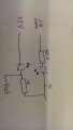
The first one shows the circuit diagram. Ive got a square wave between 0 and around 4v. Into an LED. the LED shines onto the phototransistor and I get the output from there. But the output sqaure wave looks like the sketch ive drawn. The top parts fine but the line doesnt go straight down as a normal sqaure wave.
Sorry Ive just realised ive drawn an LDR its meant to be an phototransistor. Collector to 5v. Emitter to 0v.
And please post either a scope shot or a sketch of the waveform. Depending on how the transistor is connected, the curve probably is caused by either not enough light to turn on all the way, or too much background light (not enough dark) to prevent turning off all the way.
Hi, ive posted the output. What your saying sounds like it might be right, But the output from the top of the wave is fine so there is enough darkness. Its when the wave goes down to the bottom that might mean theres not enough light ?.
In your schematic the output phototransistor is connected as an emitter follower, which is a non-inverting circuit. Therefore, when the input is high and the LED is making IR light, the output is high. That the top is flat and the corners are sharp indicates that there is enough light. The leading edge (low-to-high transition is sloped, but this could be because the input waveform is sloped, or because the output phototransistor is not very fast.
Assuming the input waveform is symmetrical (equal high and low periods), it does look like the phototransistor is having trouble turning off enough for an equally wide and flat low output voltage. One way to test this is to increase the output resistor to 10 K. The output waveform should change; better or worse, it is a clue.
I tried to simulate your case using optocouplers. The transmission coefficient of the input current to the output is typically 100% -300%. The current is set resistor, 10kOhm par value. (Iin=(5V-Vled)/10kOhm=0.4mA Iout=4V/1kOhm=4mA ---A=10=1000%). Ie current is small, and most likely you are using the type of Darlington phototransistor. These transistors have a very high coefficient of transmission, but slowly off. Correct me if I'm wrong.
I tried to simulate your case using optocouplers. The transmission coefficient of the input current to the output is typically 100% -300%. The current is set resistor, 10kOhm par value. (Iin=(5V-Vled)/10kOhm=0.4mA Iout=4V/1kOhm=4mA ---A=10=1000%). Ie current is small, and most likely you are using the type of Darlington phototransistor. These transistors have a very high coefficient of transmission, but slowly off. Correct me if I'm wrong.
The transmission coefficient is the ratio of the output current of the transistor to the current LED (ir source). Unfortunately, we have little information about your project. What is the source of the signal (frequency and amplitude)? If acceptable, reduce the 10K resistor. If the output voltage will remain the same (4V), then I'm right. Darlington has Vsat ~ 1V. Vout_max = 5V-Vsat.
 Facebook
 Google
 GitHub
 Linkedin