Square Wave is Noisy and Distorted

Thread Starter

ethicaldesign

Joined Jun 19, 2017
11
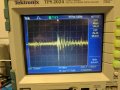
Hi, I am injecting a 20V, 400Hz Square Wave into the below circuit, but after it is stepped down through the OP AMP to a theoretical 20mV Square Wave, it is incredibly noisy. The circuit uses a Pi filter with a ferrite bead (P/N: HI1206T500R-10) with impedance of 50 ohms at 100MHz. The circuit also implements an inverting op amp to with a gain of -0.002. The Toff also appears to have a steeper rise time than the Ton and suspect this to be from capacitance. After searching the forums, I found a suggestion for using a Zener diode to help remove some of the spikes, but wanted to get input specific to my problem. I do have 0.1uF caps across the +15V and the -15V to ground. Thanks guys!

upload_2017-6-19_8-5-23.png
IMG_20170619_074226.jpg
 

Alec_t

Joined Sep 17, 2013
14,280
Welcome to AAC!
What's wrong with using a simple 2-resistor voltage divider instead of all that circuitry? If you need inversion wouldn't just a BJT suffice?
 

Thread Starter

ethicaldesign

Joined Jun 19, 2017
11
A voltage divider would definitely have been the easiest solve here, but we needed the output to be buffered and isolated from this circuit. It goes to a board that also has a high voltage motor driver on it and to keep things safe, we went this route.
 

Alec_t

Joined Sep 17, 2013
14,280
The noise on the scope trace could be random interference pickup on the scope probe lead?
Is the circuit on a breadboard or a on a well-designed pcb in a metal screening box and with proper supply decoupling?
 

AnalogKid

Joined Aug 1, 2013
10,989
Rule #1 of a digital scope - Don't ever confuse what you are seeing with what is.

Beyond that, some general purpose test set cleanup ideas:
What is the noise of the scope channel input with an open probe?
Turn on and off nearby fluorescent and LED lights and see if there is any effect on the noise amplitude.
Enable the bandwidth limiting in the vertical amplifier input. The scope bandwidth is 500,000 times greater than the fundamental being measured. Too much of a good thing picks up FM radio from Mars.
Reduce the length of the ground lead on the scope probe to 0.1". It can make contact with the ground plane surrounding the opamp, at a point nearest the output pin.

ak
 

MrChips

Joined Oct 2, 2009
30,720
What is the detection limit of the scope?
How does the opamp provide isolation?
Why not use a simple resistor voltage divider in the first place?
 

Thread Starter

ethicaldesign

Joined Jun 19, 2017
11
The noise on the scope trace could be random interference pickup on the scope probe lead?
Is the circuit on a breadboard or a on a well-designed pcb in a metal screening box and with proper supply decoupling?
Yes, the circuit is on a "well-designed" FR4 PCB and housed in a metal enclosure with chassis ground. We are measuring from a breakout box with mini banana jacks to our scope. Here is a pic of an open lead noise test:
 

Attachments

Thread Starter

ethicaldesign

Joined Jun 19, 2017
11
Rule #1 of a digital scope - Don't ever confuse what you are seeing with what is.

Beyond that, some general purpose test set cleanup ideas:
What is the noise of the scope channel input with an open probe?
Turn on and off nearby fluorescent and LED lights and see if there is any effect on the noise amplitude.
Enable the bandwidth limiting in the vertical amplifier input. The scope bandwidth is 500,000 times greater than the fundamental being measured. Too much of a good thing picks up FM radio from Mars.
Reduce the length of the ground lead on the scope probe to 0.1". It can make contact with the ground plane surrounding the opamp, at a point nearest the output pin.

ak
What is the noise of the scope channel input with an open probe?
It looks to be about 18kHz? (see pic)

Turn on and off nearby fluorescent and LED lights and see if there is any effect on the noise amplitude.
I didn't notice any changes with the lights off

Enable the bandwidth limiting in the vertical amplifier input. The scope bandwidth is 500,000 times greater than the fundamental being measured. Too much of a good thing picks up FM radio from Mars.
I will try this

Reduce the length of the ground lead on the scope probe to 0.1". It can make contact with the ground plane surrounding the opamp, at a point nearest the output pin.
I'm kind of limited with the system we have in place. I'd estimate we have about 4 inches of wire from the output.

Thanks for all your help!
 

Thread Starter

ethicaldesign

Joined Jun 19, 2017
11
What is the detection limit of the scope?
How does the opamp provide isolation?
Why not use a simple resistor voltage divider in the first place?

What is the detection limit of the scope?
upload_2017-6-19_10-7-4.png
Does this answer that question?

How does the opamp provide isolation?
We wanted to be sure that if we were drawing current somewhere on this circuit later (even just to measure it), that we wouldn't be changing the voltage. The goals is to ensure that doing the measurement of a voltage does not disturb the circuit producing the voltage to be measured. So isolation in that sense.
 

bertus

Joined Apr 5, 2008
22,270
Hello,

Looking at the scope characteristics, the most sensitive setting is 2 mV/div.

tps2024_characteristics.png

How is the noise when you short the input of the scope?

Bertus
 

Attachments

Kermit2

Joined Feb 5, 2010
4,162
You could just use an op amp buffer with a resistive divider.

Again. Why the excessive complexity for a buffered signal?
 

Thread Starter

ethicaldesign

Joined Jun 19, 2017
11
What OP amp are you using? tray a small resistor in series with the non-inverting input of the OP-amp

Check for ground loops.

Are you DC or Ac coupled with the scope?
What OP amp are you using? tray a small resistor in series with the non-inverting input of the OP-amp
OPA627AU

Are you DC or Ac coupled with the scope?
I have tried both and they both return the same result.
 

Alec_t

Joined Sep 17, 2013
14,280
If shorted probe leads are giving that much noise on the display, IMO the leads are inadequately screened or the scope grounding is suspect.
 

Deleted member 115935

Joined Dec 31, 1969
0
Uhm.

My rule of this sort of thing is, look at the screen and try to guess what it is.

Its 50 to 100 mV of "noise", on 50mV of square wave.

What gain are you running the Amp at ?
is it stable at that gain ?

Generally, op amps dont like to have gain of less than one, can you try what happens if you make the op amp a unity gain buffer ?
might give you clue if its the amp or the way your using it.

Id try zooming in on the 'noise' , see if its of an obvious frequency, may be mains or from a switch mode psu.

Also as said above.
If the scope ground and scope tip shorted together gives you anything but a flat line, your scope probes are broken.
 

Picbuster

Joined Dec 2, 2013
1,047
You did, in my view, something strange by giving a square wave voltage to the opamp and use the opamp as level switcher 20mV.
If the input goes from 0-20V the opamp goes in saturation and the results are undefined ( depending on model used).
The signal edge rise time will create an impedance (your L/c/r circuits) changing the amplification for that frequency).

that's why I do not like this type of circuits unless you want to amplify certain parts of the signal.

Picbuster
 
Top