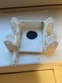
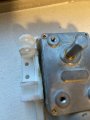
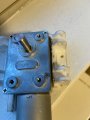
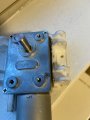
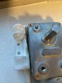
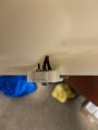
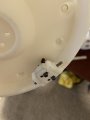
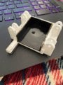
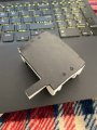
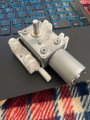
Ok, do you think if the motor housing in the above images is separated by a good layer of 1.5mm neoprene with the main board it will make some difference?
If I add the shrink wrap to the inside of the motor housing so it is no longer a loose fit do you believe this would make the sound worse?
Ok, if the neoprene has to hold the motor without being compressed I'm going to have to try and remove some of the material from the print or redesign the holder, it would take a week or 2 to get a new print ready, manufactured and sent so I'm hoping I can do something from home to make this work without resorting to a new print.
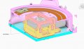
If the sound issue doesn't significantly improve after I make the adjustment to the holder and when I fix the neoprene to the base of the motor fixing and the main base as the arrow points to in the image below, I'll design a better holder and retry.
Note that this will not work if there are screw through the motor holder and into the housing since they will just conduct the vibrations. You have to isolate the parts with the neoprene. You could glue them, or devise something that a fender washer with the a flathead screw glue to each side to emulate a passed-through screw but not actually continuous.
Note that this will not work if there are screw through the motor holder and into the housing since they will just conduct the vibrations. You have to isolate the parts with the neoprene. You could glue them, or devise something that a fender washer with the a flathead screw glue to each side to emulate a passed-through screw but not actually continuous.
Hmm.. that makes a lot of sense, I never considered that but it’s a valid point. I just received some rubber washers for the screws, if I understand you correctly when your saying I need to isolate the two parts could I use the rubber washers to keep the screws physically separated from touching both the motor base and the main base so they would only be in contact with the rubber? I’ll also add neoprene to house the motor in, as well as separate the motor base and main base with neoprene. I’m not entirely sure I understand your description using a fender washer with a flathead screw to emulate a passed-through screw?
I managed to use a soldering iron to widen the Motor base so I should be able to add the neoprene without compressing it. I attached a fee images to show how it looks. The neoprene should arrive tomorrow.
I'm not really sure what size you would need, but I wouldn't go too big because you might risk pitting the rings. You might also want to place a small resistor in series with the cap...say 5 ohms.
Maybe start with 220uf then try larger if needed. (electrolytic)
Let me say this, a capacitor will only help with those short flickers those longer ones will definitely require a mechanical solution because a cap to eliminate those would be very large.
And, to clarify the receiving side is the side of the rings that receive the power from the supply. (the LEDs)
Good luck, I like what you have done so far. (lighted sculpture is kinda of my niche)
Just checking with you as the capacitors and resistors are arriving tomorrow,is this the location where I should attach the capacitor/resistor to? Just above the carbon brushes where the wires are?
You really should tag the person when you want their attention...example @Jacob1994
Yes, you connect the cap above the brushes, assuming they connect to the LEDs, you can connect them anywhere you can access easily.
And keep in mind the resistor is optional.
Also as I look at those brushes, do they have room to move side to side as well as up and down, that could be part of the problem, you really do need to keep brushes straight.
Ok great well the cap should just about fit above the carbon brushes. I may forgo the resistor if it is optional as the space is rather restrictive.
yes that’s a fair point, the holes for the carbon brushes have about a 1mm clearance. I was trying to account for any shrinkage in the 3D print but I may have overcompensated slightly. I’ll try and use something to fill the void space to keep the carbon brushes from deflecting as little as possible.
Thanks for the feedback, as always really great points!
Attached is how the motor cage now looks, the motor gently fits into the housing without pressing hard against the neoprene. I’ve also added a thicker layer of neoprene on the underside of the motor housing. I’m shaping out sections of neoprene to go along the outer edge of the base so when it is screwed to the main base its separated by neoprene as well.
By the way, less rather than more surface area in contact with the motor is one way to reduce coupling. You might want to remove material from the center of the bottom and leave strips or "feet".
By the way, less rather than more surface area in contact with the motor is one way to reduce coupling. You might want to remove material from the center of the bottom and leave strips or "feet".
Ah ok that's a great point, I'll see how the sound of the motor is with this configuration once I've managed to finish the ring of neoprene around the base and let you know how it goes. If its still too loud I'll try making that adjustment to leave feet or strips
So the motor seems to be quieter now which is great, however I recently cleaned the copper rings to try and make them less tarnished, using a solution of vinegar, flour and salt, now the copper rings hardly seem to conduct any current! I placed a single LED around the rings and it only gives off a dim flicker when I try placing it in about 10 different locations.
The strip light does not come on at all. I have run a fine set of tweezers through any gaps that appeared to have some of the solution in it, but this doesn't seem to have improved it at all. I checked underneath the rings and the wires are still fine and the motor and speakers are all working fine. Might they work after a while if there is solution that possibly hasn't dried off or have I ruined the copper rings and need to get a replacement?
I've had a read, is there any suggestion you may have how I can fix this? Have I spread up this process accidentally when I was trying to clean the copper? :/
I've had a read, is there any suggestion you may have how I can fix this? Have I spread up this process accidentally when I was trying to clean the copper? :/

 Facebook
 Google
 GitHub
 Linkedin




 I'll keep you posted how it goes