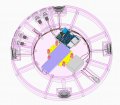
So all components are now good, I've sent the first piece of the project to be 3D printed as a test for quality.
In preparation for when all of the prints are ready to assemble, I'm trying to create the logic for the wiring in the model so I can go through it step by step checking wiring off as I go along.
I've by no means finished modelling the basic wiring that is straightforward and doesn't require much thought, I should have that done in the next day or so.
The wiring setup I want to make sure I get right is as follows:
- Master power button to power all 3 systems
- Ability to turn on/off the 3 systems (lights, motor and audio) separately if needed. i.e. keep motor and lights with no music, etc
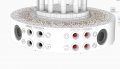
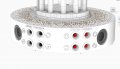
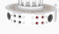
I hope the attached image with the control buttons helps to explain what I'm hoping to achieve. I'm pretty confident there shouldn't be any trouble setting up the audio control wiring since they are simple single circuits.
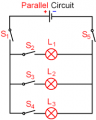
I'm trying to make sure when I have the wiring setup for the motor, lighting & audio that I get this correct as it gets a little bit messy with all the wiring crammed into the box. I want to make sure I have the option to turn all of the 3 off by pressing the single power button but am also hoping it will be possible to incorporate a power button for each of the 3 (motor, lights and audio) so in the instance that one or 2 of the systems wanted to be shut off this option would be possible.
I hope I explained what I'm trying to do in a clear manner. Please let me know if not and I'll try to explain it differently.
And if I wanted to close the power for one of these sub power how would I set this up without breaking the circuit?
If I’m understanding correctly I need to create a circuit that connects from the power jack to all 3 components whilst at some point in the circuit connecting to the master power switch.
For powering individual systems I need to wire to only one system, the motor for example, and connect this to the appropriate switch?
Me too Bob! After I get the first section of the model print delivered in the next few days and check it for accuracy I’ll order the rest and hopefully get it together fairly quickly!
Ah that actually makes sense to me! Thank you
And am I right to assume I'll have to connect the wiring from the 3 separate switches to the pins on the master switch or can I connect it along the wire that links to the master? I'm thinking I'll need to connect to the pins on the master switch.
What do you mean by wiring it twice?
To me that means wiring it, removing the wires and wiring it again.
With one ON/OFF switch you can control the power to the entire project.
If you want to control three sections of the project independently then you will need three switches.
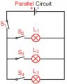
If you want to control the entire project with one switch AND be able to turn off individual sections then you will need four switches.
What do you mean by wiring it twice?
To me that means wiring it, removing the wires and wiring it again.
With one ON/OFF switch you can control the power to the entire project.
If you want to control three sections of the project independently then you will need three switches.
If you want to control the entire project with one switch AND be able to turn off individual sections then you will need four switches.
I mean I'd need to wire all 3 of my devices to the master switch and then wire each of the devices to the separate switches as well? I have my switch setup to the last configuration you described.
There is a master switch in your service panel.
Then there is a separate wall switch to the room light in each room.
There are two wires going to every light bulb. The switch breaks the circuit on one side only, the LINE wire.
There is a master switch in your service panel.
Then there is a separate wall switch to the room light in each room.
There are two wires going to every light bulb. The switch breaks the circuit on one side only, the LINE wire.
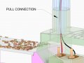
Good news, I've ordered all of the 3d Prints so just have to wait for them to arrive now. Won't be able to start wiring until July 10th when I'm back from vacation. There was one last thing I was hoping to try, which is to have a click in connection for the wires between where the base and top of the model connect so when I remove the top and bottom of the model I don't pull the wires connected to the LED lights above. Is there any type of component anyone could suggest?
Thanks Annie, this is really the sort of thing I need! My only constraint is that the opening is a circle with a diameter of 4mm. Is something like this also an option?

 Facebook
 Google
 GitHub
 Linkedin