SoftstartCircuit_LTSpice simulation

Thread Starter

Nickmar2877

Joined Dec 6, 2021
19
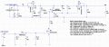
Please help for the attached circuit, further explain how soft start circuit works in M2 (PMOS) with RC circuit, computation and the voltage divider with zener diode with BJT (PNP), how it works, for the first PMOS(M1) it will only flow in body diode act as reverse polarity protection.
 

Attachments

After power-on the Vgs of M2 rises from 0V to about 10V (given by R4&R5 divider) very slowly because of C3 cap, holding M2 in linear region, so it limits the current flowing to output.
At some level of M2 Vgs (C3 voltage) like 4V the mosfet is fully conducting so it doesn’t limit the output current anymore.

Btw, the zener overvoltage protection is very slow here because after overvoltage the PNP has to discharge the C3 as first to close the M2. Take quite a lot of time.
 
Last edited:
Top