Soft Star of IC pin

Thread Starter

somaye2022

Joined Mar 23, 2022
100
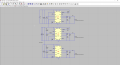
Hello everyone. I am designing 3 step down converters from a source of 5V for three output voltages of 3.3V, 1.8V and 1.2V. My issue here is that I want the output voltage of the first converter to reach 3.3V first, then I want the second converter to start for 1.8V output voltage and at the end I want the third converter to start for the 1.2V output voltage sequncial. As you can see in the attachment, the second converter starts before the first one reaches the exact value of 3.3V if I use Css of 0.01u as recommended in the detasheet. But if I change the Css to 1nF then it works fine. Do you have any idea how I could fix the problem with 0.01uF Css?

Thank you with best regards
 

Attachments

dl324

Joined Mar 30, 2015
16,943
What is it that you're trying to do where you need the 3.3V regulator to be at exactly 3.3V before the other converters start? The regulators will have a tolerance and startup time should be relatively fast.
 

DickCappels

Joined Aug 21, 2008
10,187
The solution might be in the use of the RUN pin. From the datasheet:

"RUN (A3): Run Control Input of the Switching Mode
Regulator. Enables chip operation by tying RUN above
1.2V. Pulling it below 1.1V shuts down the part. Do not
leave floating."

You can use comparitors, resistors, and a low voltage reference like the LM385-1.2 to monitor the outputs of the first two supplies and then raise the RUN pin when the power supplies reach the desired outputs. A little hysteresis in the comparitor can reduce chances of oscillation.
 

Thread Starter

somaye2022

Joined Mar 23, 2022
100
What is it that you're trying to do where you need the 3.3V regulator to be at exactly 3.3V before the other converters start? The regulators will have a tolerance and startup time should be relatively fast.
I require the regulator for input of an FPGA Boards, and one of the requirements is for regulators to work sequentially to not use a high dynamic current.
 

Thread Starter

somaye2022

Joined Mar 23, 2022
100
The solution might be in the use of the RUN pin. From the datasheet:

"RUN (A3): Run Control Input of the Switching Mode
Regulator. Enables chip operation by tying RUN above
1.2V. Pulling it below 1.1V shuts down the part. Do not
leave floating."

You can use comparitors, resistors, and a low voltage reference like the LM385-1.2 to monitor the outputs of the first two supplies and then raise the RUN pin when the power supplies reach the desired outputs. A little hysteresis in the comparitor can reduce chances of oscillation.
Thanks for your reply, I have adjusted the PGOOD of RUN. But because of space limitations without any other changes. The problem was solved, but since I use a dynamic load, -0.6 V minus voltage comes to the output of the third one. See attachment. Why such negative output voltage is coming out?LTM4623.raw_.png
 

Thread Starter

somaye2022

Joined Mar 23, 2022
100
Is the negative problem there is you replace your load with a fixed resistor?
Please post your .asc file. It is hard to see your schematic.
NO, its not there
Is the negative problem there is you replace your load with a fixed resistor?
Please post your .asc file. It is hard to see your schematic.
No, its not there anymore with fixed resistor.
 

Attachments

ronsimpson

Joined Oct 7, 2019
3,045
No, its not there anymore with fixed resistor.
A "current load" will demand current. If the supply can not make current the load will pull negative until there is current.

Your load is like a constant current source, except negative. A current source will push current oven if it goes to millions of volts to do that. Your load will pull current until the internal diodes in the IC turn on.

There really is not a constant current load in the real world.
I do not know how to make a piecewise linear function for resistance.
 
Top