 Facebook
 Google
 GitHub
 Linkedin
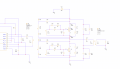
Hello experts, I am currently working on a tesla coil design, it involves a half bridge inverter and I ran into some problems, so I though I'd come here for some advise. Below is the half bridge I made, it's driven by a gate drive transformer(powered by a gate drive IC), it has 320VDC as the input, 2 IGBTs as transistors, a LC as the load, and a switching frequency of around 154kHz, I also added a RC snubber for transients.
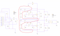
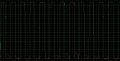
My first question has to do with soft switching, I wanted to decrease the power loss and heat so I did some research and added a soft switching circuit(the red part in the picture below, I believe it is called the "passive lossless snubber"), but the circuit doesn't seem to be working as there are still overlaps between the voltage and current during turn on and off(second picture below, green is the voltage and red is the current, see the nodes on the first picture for referrence), and the power loss can go up to a couple thousand watts which is scary. It might also be the values of the soft switching circuit not being correct but I cannot find an article on how to calculate the values, so if anyone is knowlegable please help, and if the implementation is just wrong please tell me also.
*also these are all done in PSpice simulation


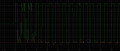
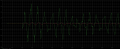
And here's the second question, from what I see on other half bridge projects on the internet, their voltage and current graph is pretty different from mine, their voltage and current all show a square wave-like form, but mine just looks really wierd(below is a clearer picture of the full result). You can see that it starts of with a constant 160V, then the voltage across the IGBT has a lot of wierd spikes, it also doesn't fully reach 0 when it's turned off, then only after a while will it finally become normal. As for the current it's just wierd and I dont even know what is happening. I believe if all is operating normally then both current and voltages should both look like square waves, and when V is high I should be low and vice versa. If you know please explain what causes these wierd behaviors and what I might do to fix it

Finally I have one last question, for most tesla coils I see online, they have a peak current of hundreds of Amps going through the primary coil, but I seem to only be getting 10-20 or even lower current(below is a graph that shows current(red) and voltage(green), refer to the nodes), could some components be limiting the current? Please comment if you find something.


*
IGBT: AFGB40T65RQDN
Gate Drive IC: UCC21520
Also I'm pretty sure nothing is wrong with the gate drive, I tested everything regarding that.
*
Sorry if this is a lot, I am quite new to all this so there are definetely a lot of things that I missed or overlooked, your help will be much appreciated, thank you in advanced, also if you need more details please let me know, thanks!
My first question has to do with soft switching, I wanted to decrease the power loss and heat so I did some research and added a soft switching circuit(the red part in the picture below, I believe it is called the "passive lossless snubber"), but the circuit doesn't seem to be working as there are still overlaps between the voltage and current during turn on and off(second picture below, green is the voltage and red is the current, see the nodes on the first picture for referrence), and the power loss can go up to a couple thousand watts which is scary. It might also be the values of the soft switching circuit not being correct but I cannot find an article on how to calculate the values, so if anyone is knowlegable please help, and if the implementation is just wrong please tell me also.
*also these are all done in PSpice simulation
And here's the second question, from what I see on other half bridge projects on the internet, their voltage and current graph is pretty different from mine, their voltage and current all show a square wave-like form, but mine just looks really wierd(below is a clearer picture of the full result). You can see that it starts of with a constant 160V, then the voltage across the IGBT has a lot of wierd spikes, it also doesn't fully reach 0 when it's turned off, then only after a while will it finally become normal. As for the current it's just wierd and I dont even know what is happening. I believe if all is operating normally then both current and voltages should both look like square waves, and when V is high I should be low and vice versa. If you know please explain what causes these wierd behaviors and what I might do to fix it
Finally I have one last question, for most tesla coils I see online, they have a peak current of hundreds of Amps going through the primary coil, but I seem to only be getting 10-20 or even lower current(below is a graph that shows current(red) and voltage(green), refer to the nodes), could some components be limiting the current? Please comment if you find something.
*
IGBT: AFGB40T65RQDN
Gate Drive IC: UCC21520
Also I'm pretty sure nothing is wrong with the gate drive, I tested everything regarding that.
*
Sorry if this is a lot, I am quite new to all this so there are definetely a lot of things that I missed or overlooked, your help will be much appreciated, thank you in advanced, also if you need more details please let me know, thanks!
Attachments
-
 55 KB Views: 6
 -
 89.8 KB Views: 5
 -
 38.8 KB Views: 3
 -
 58.4 KB Views: 2
 -
 61 KB Views: 2


