 Facebook
 Google
 GitHub
 Linkedin
Hello,
I am trying to measure the frequency response of SMPS in general. I am sensing the feedback and injected signal with a isolation transformer and resistor at the feedback loop. My problem is that my gain at low frequencies is always below 0dB. Why? How can I find the crossover frequency to establish the phase margin?
To simplify things we have first used a 5V power supply with output voltage sense capability as shown below.

We broke the loop at Remote (+) Sense and inserted the 22 ohms resistor. The power supply was loaded to 2A at high/low line.
"Aside from that the frequency response analyzer should have instructions on how to calibrate it and set it up for consistency"
We are using differential voltage probes connected from either side of 22 ohms resistor to (-) OUT. The attenuation ratio is 1/20. I am wondering how to set this in the AP300 software. There is a button called probe calibration but it requires a user defined file to be uploaded. I do not know how to do this. Currently this is not done. I tested a passive LC network, the gain and phase response were as per calculation.
Now the problem for the 5V power supply is that I cannot see the gain go above 0dB at low frequencies. As per the TI document in the link below power supply gain should be positive for frequencies up to the crossover frequency of few KHz and then it should go negative.
www.ti.com/.../snva364a.pdf

However, the waveforms I have got are not similiar. They are shown below :

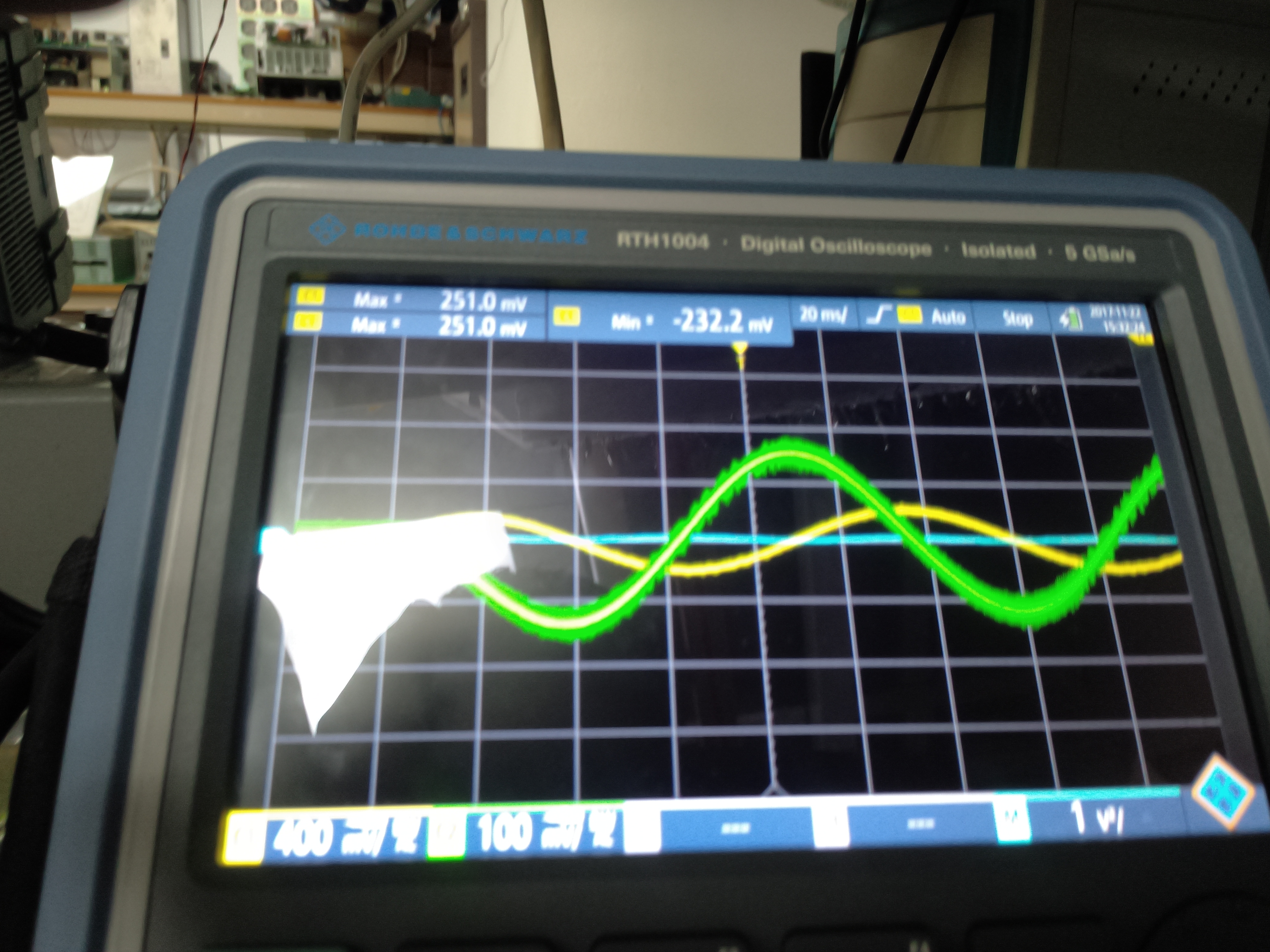
I have hooked up a oscilloscope to see if the output sine wave amplitude (green) is becoming greater than the incoming Sine wave amplitude (yellow) for low frequencies. 20log (out/In) should be positive for low frequencies but the AP300 analyzer does not show that. I have checked to see if the output and input are interchanged wrongly. No. They are connected correctly. Do you think probe calibration is still the problem or is there anything wrong in my setup? The time domain signals are shown below.

Please think about it. Thanks.
I am trying to measure the frequency response of SMPS in general. I am sensing the feedback and injected signal with a isolation transformer and resistor at the feedback loop. My problem is that my gain at low frequencies is always below 0dB. Why? How can I find the crossover frequency to establish the phase margin?
To simplify things we have first used a 5V power supply with output voltage sense capability as shown below.

We broke the loop at Remote (+) Sense and inserted the 22 ohms resistor. The power supply was loaded to 2A at high/low line.
"Aside from that the frequency response analyzer should have instructions on how to calibrate it and set it up for consistency"
We are using differential voltage probes connected from either side of 22 ohms resistor to (-) OUT. The attenuation ratio is 1/20. I am wondering how to set this in the AP300 software. There is a button called probe calibration but it requires a user defined file to be uploaded. I do not know how to do this. Currently this is not done. I tested a passive LC network, the gain and phase response were as per calculation.
Now the problem for the 5V power supply is that I cannot see the gain go above 0dB at low frequencies. As per the TI document in the link below power supply gain should be positive for frequencies up to the crossover frequency of few KHz and then it should go negative.
www.ti.com/.../snva364a.pdf
However, the waveforms I have got are not similiar. They are shown below :

I have hooked up a oscilloscope to see if the output sine wave amplitude (green) is becoming greater than the incoming Sine wave amplitude (yellow) for low frequencies. 20log (out/In) should be positive for low frequencies but the AP300 analyzer does not show that. I have checked to see if the output and input are interchanged wrongly. No. They are connected correctly. Do you think probe calibration is still the problem or is there anything wrong in my setup? The time domain signals are shown below.
Please think about it. Thanks.


